- Catalogs
- Copley Controls
- Accelnet Plus CANopen 2-Axis Module
Accelnet Plus CANopen 2-Axis Module
1 /32Pages
Accelnet Plus CANopen 2-Axis Module
1 /32Pages
Catalog excerpts

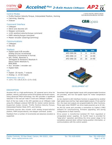
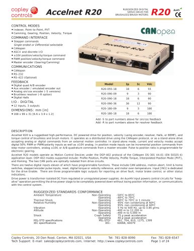
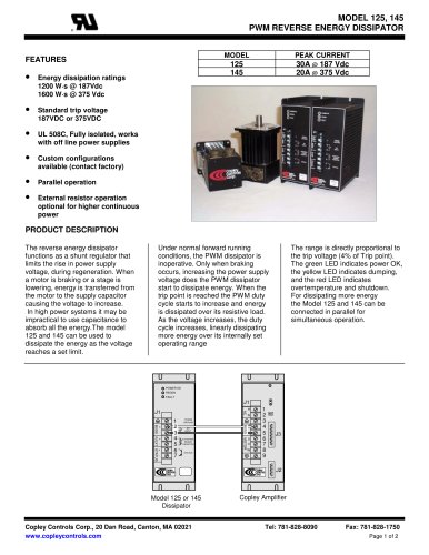
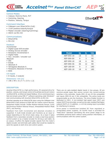
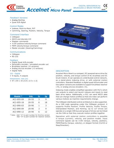
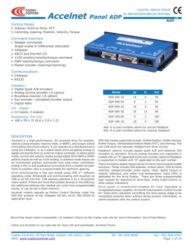
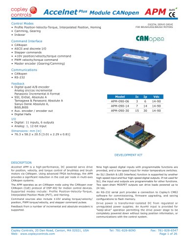
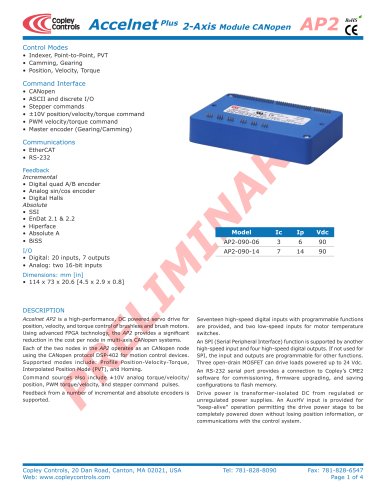
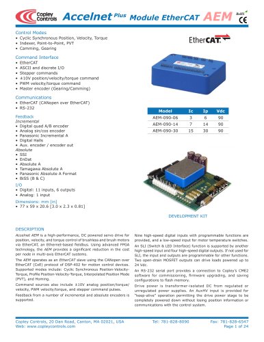
Accelnet Plus 2-Axis Module CANopen AP2 Control Modes RoHS 2-AXIS DIGITAL SERVO DRIVE FOR BRUSHLESS/BRUSH MOTORS • Profile Position-Velocity-Torque, Interpolated Position, Homing • Camming, Gearing • Indexer R Command Interface • • • • • • CANopen ASCII and discrete I/O Stepper commands ±10V position/velocity/torque command PWM velocity/torque command Master encoder (Gearing/Camming) Communications • CANopen • RS-232 Feedback • Digital quad A/B encoder Analog sin/cos incremental Panasonic Incremental A Format • SSI, EnDat, Absolute A, Tamagawa & Panasonic Absolute A Sanyo Denki Absolute A, BiSS,BiSS • Aux. encoder / encoder out • Digital Halls Model Ic Ip Vdc AP2-090-06 3 6 14-90 AP2-090-14 7 14 14-90 AP2-090-30 15 30 14-90 I/O • Digital: 20 inputs, 7 outputs • Analog: 2, 12-bit inputs Dimensions: mm [in] • 114 x 73 x 20.6 [4.5 x 2.9 x 0.8] DEVELOPMENT KIT DESCRIPTION Accelnet AP2 is a high-performance, DC powered servo drive for position, velocity, and torque control of brushless and brush motors. Using advanced FPGA technology, the AP2 provides a significant reduction in the cost per node in multi-axis CANopen systems. Each of the two nodes in the AP2 operates as an CANopen node using the CANopen protocol DSP-402 for motion control devices. Supported modes include: Profile Position-Velocity-Torque, Interpolated Position Mode (PVT), and Homing. Command sources also include ±10V analog torque/velocity/ position, PWM torque/velocity, and stepper command pulses. Feedback from a number of incremental and absolute encoders is supported. Copley Controls, 20 Dan Road, Canton, MA 02021, USA Web: www.copleycontrols.com Seventeen high-speed digital inputs with programmable functions are provided, and two low-speed inputs for motor temperature switches. An SLI (Switch & LED Interface) function is supported by another high-speed input and four high-speed digital outputs. If not used for SLI, the input and outputs are programmable for other functions. Three open-drain MOSFET can drive loads powered up to 24 Vdc. An RS-232 serial port provides a connection to Copley’s CME2 software for commissioning, firmware upgrading, and saving configurations to flash memory. Drive power is transformer-isolated DC from regulated or unregulated power supplies. An AuxHV input is provided for “keep-alive” operation permitting the drive power stage to be completely powered down without losing position information, or communications with the control system. Tel: 781-828-8090 Fax: 781-828-6547 Page 1 of 32
Open the catalog to page 1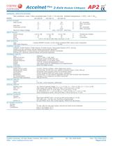
Accelnet Plus 2-Axis Module CANopen AP2 RoHS GENERAL SPECIFICATIONS Test conditions: Load = Wye connected load: 2 mH + 2 Ω line-line. Ambient temperature = 25°C, +HV = HVmax MODEL AP2-090-06 OUTPUT POWER Peak Current Peak time Continuous current Maximum Output Voltage INPUT POWER HVmin~HVmax Ipeak Icont Aux HV PWM OUTPUTS Type PWM ripple frequency AP2-090-14 6 4.2 1 3 2.1 14 10 1 7 5 AP2-090-30 30 21.2 1 15 10.6 Vout = HV*0.97 - Rout*Iout +14 to +90 +14 to +90 +14 to +90 12 28 30 6 14 15 +14 to +HV Vdc @ 500 mAdc maximum, 2.5 W A A s A A DC, sinusoidal RMS, sinusoidal Sec DC, sinusoidal RMS,...
Open the catalog to page 2
Accelnet Plus 2-Axis Module CANopen AP2 RoHS FEEDBACK (each axis) Incremental: Digital Incremental Encoder Quadrature signals, (A, /A, B, /B, X, /X), differential (X, /X Index signals not required) 5 MHz maximum line frequency (20 M counts/sec) 26LS32 differential line receiver with 121 Ω terminating resistor between complementary inputs Analog Incremental Encoder Sin/cos format (sin+, sin-, cos+, cos-), differential, 1 Vpeak-peak, ServoTube motor compatible Absolute: SSI Clock (X, /X), Data (S, /S) signals, 4-wire, clock output from AEP, data returned from encoder EnDAT Clock (X, /X), Data (S,...
Open the catalog to page 3
Accelnet Plus 2-Axis Module CANopen AP2 RoHS CANOPEN Based on the CAN V2.0b physical layer, a robust, two-wire communication bus originally designed for automotive use where low-cost and noise-immunity are essential, CANopen adds support for motion-control devices and command synchronization. The result is a highly effective combination of data-rate and low cost for multi-axis motion control systems. Device synchronization enables multiple axes to coordinate moves as if they were driven from a single control card. CANOPEN COMMUNICATION Accelnet uses the CAN physical layer signals CANH, CANL,...
Open the catalog to page 4
Accelnet Plus 2-Axis Module CANopen AP2 RoHS COMMAND INPUTS ANALOG COMMAND INPUT The analog inputs have a ±10 Vdc range. As a reference input it can take position/velocity/torque commands from a controller. Axis A(B) D/A CME2 -> Basic Setup -> Operating Mode Options Ref(+) ±10V P5/3(5) Ref(-) - Vref 5k + P5/4(6) Sgnd 1.25V P5/7,8 DIGITAL COMMAND INPUTS Digital commands are single-ended format and should be sourced from devices with active pull-up and pull-down to take advantage of the high-speed inputs. The active edge (rising or falling) is programmable for the Pulse/Dir and CU/CD formats. DIGITAL...
Open the catalog to page 5
Accelnet Plus 2-Axis Module CANopen AP2 RoHS CANOPEN ALIAS (NODE ADDRESS) SWITCHES The SLI (Switch & LED Interface) port takes in the 8 signals from the two BCD encoded switches that set the CANopen alias address and controls the LEDs on the CANopen port connectors. The graphic below shows the circuit for reading the CANopen address switches. The 74HC165 works as a parallel-in/serial-out device. The 10k pull-down resistors pull the shift register inputs to ground when the AP2 is initializing. In the graphics below, switch SW13 is “S2” and SW12 is “S1”. The values of S1 are 16~255 and of S2 are...
Open the catalog to page 7
Accelnet Plus 2-Axis Module CANopen AP2 RoHS MOTOR CONNECTIONS Motor connections consist of: phases, Halls, encoder, thermal sensor, and brake. The phase connections carry the drive output currents that drive the motor to produce motion. The Hall signals are three digital signals that give absolute position feedback within an electrical commutation cycle. The encoder signals give position feedback and are used for velocity and position modes, as well as sinusoidal commutation. A thermal sensor that indicates motor overtemperature is used to shut down the drive to protect the motor. A brake can...
Open the catalog to page 8All Copley Controls catalogs and technical brochures
 XenusPLUS Compact EtherCAT XEC
30 Pages
 XenusPLUS Compact CANopen XPC
30 Pages
 Control Networks
8 Pages
 R-Series Guide
8 Pages
 Selection Guide
24 Pages
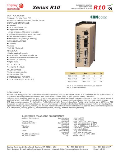 Xenus R10
30 Pages
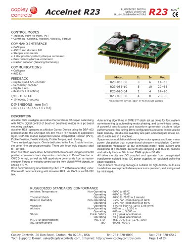 Accelnet R23
24 Pages
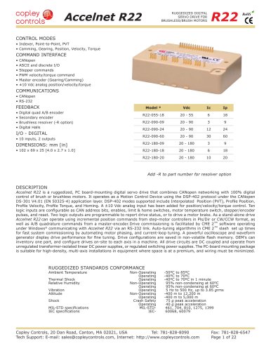 Accelnet R22
22 Pages
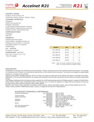 Accelnet R21
24 Pages
 Accelnet R20
24 Pages
 Accelus Card Development Kit
6 Pages
 Accelus Card
8 Pages
 ASP-X2 Accelus Panel Dual
10 Pages
 Junus
Junus10 Pages
 CAN-PCI-02
2 Pages
 CAN-IPM-01
8 Pages
 Bantam
18 Pages
 Bantam R30
18 Pages
 503
5036 Pages
 Power Supply Subsystem
8 Pages
 Shunt Regulator
2 Pages
 Xenus PLUS 2-Axis CANopen
34 Pages
 Xenus RoHS PLUS CANopen
28 Pages
 Xenus PLUS 2-Axis EtherCAT
34 Pages
 Xenus PLUS EtherCAT
28 Pages
 Xenus Edge Filter
16 Pages
 Regen Resistors
24 Pages
 Xenus Micro
24 Pages
 Accelus Card Development Kit
6 Pages
 Accelus Card
8 Pages
 Accelus Panel
10 Pages
 Xenus XTL
30 Pages
 Accelnet Plus EtherCAT Panel
18 Pages
 Accelnet Micro Module and Kit
24 Pages
 Accelnet Micro Panel
24 Pages
 Accelnet Module Development Kit
8 Pages
 Accelnet Module
14 Pages
 Accelnet Panel ADP
24 Pages


- Digital I/O
- Analog I/O
- Servo-amplifier
- Motor controller
- DC servo-amplifier
- Fieldbus servo-drive
- DC motor controller
- Stepper motor controller
- AC servo-amplifier
- Communication interface card
- Brushless servo drive
- Compact servo-amplifier
- EtherCAT servo-amplifier
- Digital servo-amplifier
- Industrial interface expansion card
- CANopen servo-amplifier
- CANopen I/O
- Brushless motor control
- Digital input motor controller
- I/O card