
- Catalogs
- Copley Controls
- Accelnet Micro Panel

- Products
- Catalogs
- News & Trends
- Exhibitions
Accelnet Micro Panel
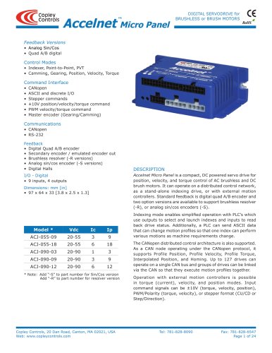
Accelnet Micro Panel
Catalog excerpts
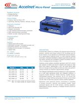
RoHS Copley Controls, 20 Dan Road, Canton, MA 02021, USA Tel: 781-828-8090 Fax: 781-828-6547 Web: www.copleycontrols.com Page 1 of 24 DIGITAL SERVODrive for BRUSHLESS or BRUSH MOTORS Accelnet Micro Panel ™ Feedback Versions • Analog Sin/Cos • Quad A/B digital Control Modes • Indexer, Point-to-Point, PVT • Camming, Gearing, Position, Velocity, Torque Command Interface • CANopen • ASCII and discrete I/O • Stepper commands • ±10V position/velocity/torque command • PWM velocity/torque command • Master encoder (Gearing/Camming) Communications • CANopen • RS-232 Feedback • Digital Quad A/B encoder • Secondary encoder / emulated encoder out • Brushless resolver (-R versions) • Analog sin/cos encoder (-S versions) • Digital Halls I/O - Digital • 9 inputs, 4 outputs Dimensions: mm [in] • 97 x 64 x 33 [3.8 x 2.5 x 1.3] d escription Accelnet Micro Panel is a compact, DC powered servo drive for position, velocity, and torque control of AC brushless and DC brush motors. It can operate on a distributed control network, as a stand-alone indexing drive, or with external motion controllers. Standard feedback is digital quad A/B encoder and two option versions are available to support brushless resolver (-R), or analog sin/cos encoders (-S). Indexing mode enables simplified operation with PLC’s which use outputs to select and launch indexes and inputs to read back drive status. Additionally, a PLC can send ASCII data that can change motion profiles so that one index can perform various motions as machine requirements change. The CANopen distributed control architecture is also supported. As a CAN node operating under the CANopen protocol, it supports Profile Position, Profile Velocity, Profile Torque, Interpolated Position, and Homing. Up to 127 drives can operate on a single CAN bus and groups of drives can be linked via the CAN so that they execute motion profiles together. Operation with external motion controllers is possible in torque (current), velocity, and position modes. Input command signals can be ±10V (torque, velocity, position), PWM/Polarity (torque, velocity), or stepper format (CU/CD or Step/Direction). * Note: Add “-S” to part number for Sin/Cos version Add “-R” to part number for resolver version Model * Vdc Ic Ip ACJ-055-09 20-55 3 9 ACJ-055-18 20-55 6 18 ACJ-090-03 20-90 1 3 ACJ-090-09 20-90 3 9 ACJ-090-12 20-90 6 12
Open the catalog to page 1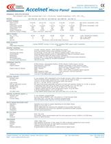
RoHS Copley Controls, 20 Dan Road, Canton, MA 02021, USA Tel: 781-828-8090 Fax: 781-828-6547 Web: www.copleycontrols.com Page 2 of 24 Accelnet Micro Panel DIGITAL SERVODrive for BRUSHLESS or BRUSH MOTORS ™ GENERAL SPECIFICATIONS Test conditions: Load = Wye connected load: 2 mH + 2 Ù line-line. Ambient temperature = 25°C, +HV = HVmax MODEL ACJ-055-09 ACJ-055-18 ACJ-090-03 ACJ-090-09 ACJ-90-12 Output Power Peak Current 9 (6.36) 18 (12.73) 3 (2.12) 9 (6.36) 12 (8.5) Adc (Arms, sinusoidal), ±5% Peak time 1 1 1 1 1 Sec Continuous current 3 (2.12) 6 (4.24) 1 (0.71) 3 (2.12) 6 (4.24) Adc (Arms, sinusoidal),...
Open the catalog to page 2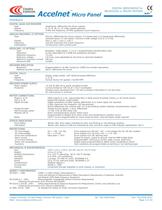
RoHS Copley Controls, 20 Dan Road, Canton, MA 02021, USA Tel: 781-828-8090 Fax: 781-828-6547 Web: www.copleycontrols.com Page 3 of 24 DIGITAL SERVODrive for Accelnet BRUSHLESS or BRUSH MOTORS Micro Panel ™ FEEDBACK Digital quad aigital quad aigital quad a/b Encoder Type Quadrature, differential line driver outputs Signals A, /A, B, /B, (X, /X, index signals optional) Frequency 5 MHz line frequency, 20 MHz quadrature count frequency Analog Encodnalog Encoder (-S OPTION) Type Sin/cos, differential line driver outputs, 0.5 Vpeak-peak (1.0 Vpeak-peak differential) centered about 2.5 Vdc typical....
Open the catalog to page 3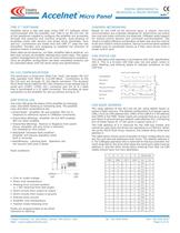
RoHS AMP statusstatusstatus LED A bi-color LED gives the status of the amplifier by changing color, and either blinking or remaining solid. The possible color and blink combinations are: • Green/Solid: Amplifier OK and enabled. Will run in response to reference inputs or CANopen commands. • Green/Slow-Blinking: Amplifier OK but NOT-enabled. Will run when enabled. • Green/Fast-Blinking: Positive or Negative limit switch active. Amplifier will only move in direction not inhibited by limit switch. • Red/Solid: Transient fault condition. Amplifier will resume operation when fault is removed. • Red/Blinking:...
Open the catalog to page 4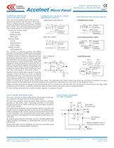
RoHS Current orVelocityPolarity orDirection[IN7][IN8]Duty = 0~100%Current orVelocityNo function[IN7][IN8]Duty = 50% ±50%PositionmagnitudePositionIncrement orDecrement[IN7][IN8]PulseDirectionMaster Enc.Ch. AMaster Enc.Ch. B[IN8][IN7]ENCABCh. ACh. BPos++Pos--PositionIncreasePositionDecrease[IN7][IN8]CW (or CU)CCW (or CD)-+37.4k37.4k5k5k1.5V-+Ref(+)Ref(-)5.36k ±10 V Analog nalog Input Copley Controls, 20 Dan Road, Canton, MA 02021, USA Tel: 781-828-8090 Fax: 781-828-6547 Web: www.copleycontrols.com Page 5 of 24 DIGITAL SERVODrive for Accelnet BRUSHLESS or BRUSH MOTORS Micro Panel ™ COMMAND Inputs...
Open the catalog to page 5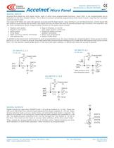
RoHS Copley Controls, 20 Dan Road, Canton, MA 02021, USA Tel: 781-828-8090 Fax: 781-828-6547 Web: www.copleycontrols.com Page 6 of 24 Accelnet Micro Panel DIGITAL SERVODrive for ™ BRUSHLESS or BRUSH MOTORS +5V[OUT1][OUT2][OUT3][OUT4]1k33nF10k+5V10k74HC14[IN1][IN2][IN3]Programmable1/033nF10k+5V10k74HC14[IN4]*[IN5]Programmable1/0* 4.99k* [IN5] connects to J4 formotor temperature sensor*3.3nF100 pF10k+5V1.0 k74HC14[IN6][IN7][IN8][IN9]Programmable1/0 DIGITAL OUTPUTS Digital outputs are open-drain MOSFETs with 1 kÙ pull-up resistors to +5 Vdc. These can sink up to 100 mAdc from external loads operating...
Open the catalog to page 6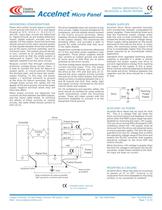
RoHS MOTORMot UMot VMot W+HVGndKeep as shortas possibleEquipment frameEarthKeep connections as close as possible."Star" ground to a common point is bestControllerDriveSignal GndControlI/OPowerSupply+-Frame GroundFrame Ground Copley Controls, 20 Dan Road, Canton, MA 02021, USA Tel: 781-828-8090 Fax: 781-828-6547 Web: www.copleycontrols.com Page 7 of 24 DIGITAL SERVODrive for Accelnet BRUSHLESS or BRUSH MOTORS Micro Panel ™ GROUNDING CONSIDERATIONS Power and control circuits share a common circuit-ground (HV Gnd on J3-4, and Signal Ground on J2-5, J4-6 & 11, J5-2,9,15,17, and 28). Input logic circuits...
Open the catalog to page 7All Copley Controls catalogs and technical brochures
 XenusPLUS Compact EtherCAT XEC
30 Pages
 XenusPLUS Compact CANopen XPC
30 Pages
 Control Networks
8 Pages
 R-Series Guide
8 Pages
 Selection Guide
24 Pages
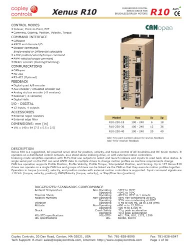 Xenus R10
30 Pages
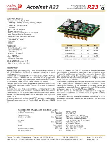 Accelnet R23
24 Pages
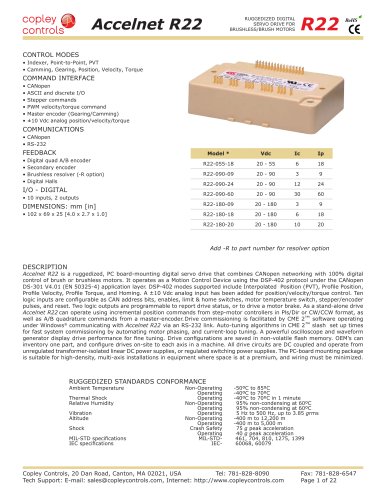 Accelnet R22
22 Pages
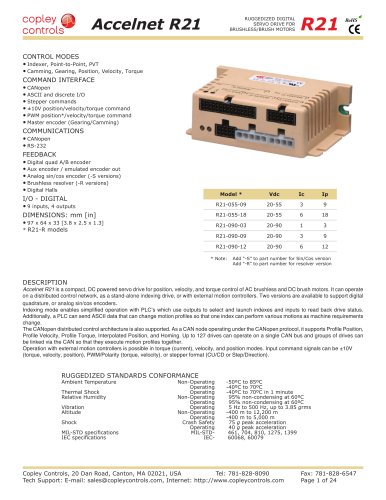 Accelnet R21
24 Pages
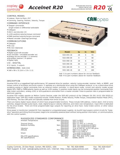 Accelnet R20
24 Pages
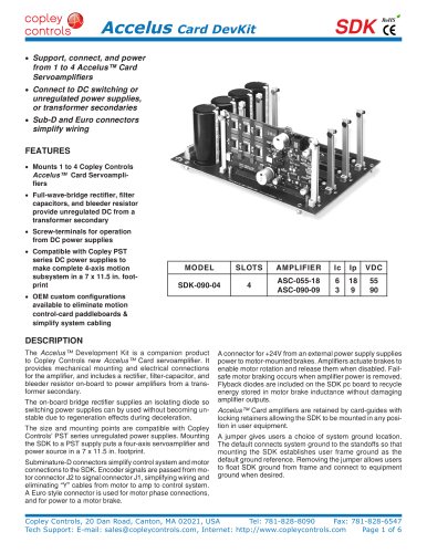 Accelus Card Development Kit
6 Pages
 Accelus Card
8 Pages
 ASP-X2 Accelus Panel Dual
10 Pages
 Junus
Junus10 Pages
 CAN-PCI-02
2 Pages
 CAN-IPM-01
8 Pages
 Bantam
18 Pages
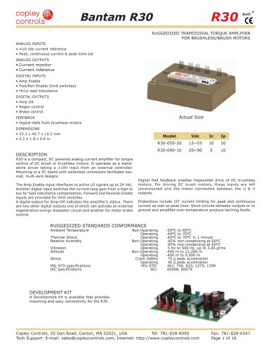 Bantam R30
18 Pages
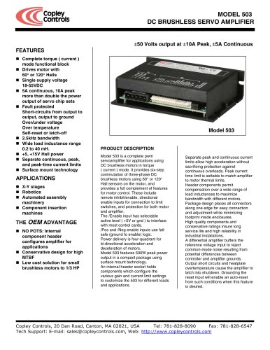 503
5036 Pages
 Power Supply Subsystem
8 Pages
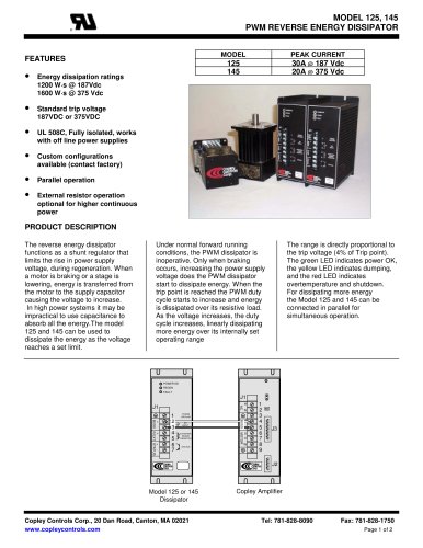 Shunt Regulator
2 Pages
 Xenus PLUS 2-Axis CANopen
34 Pages
 Xenus RoHS PLUS CANopen
28 Pages
 Xenus PLUS 2-Axis EtherCAT
34 Pages
 Xenus PLUS EtherCAT
28 Pages
 Xenus Edge Filter
16 Pages
 Regen Resistors
24 Pages
 Xenus Micro
24 Pages
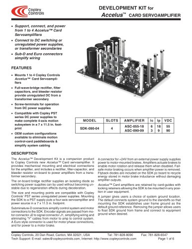 Accelus Card Development Kit
6 Pages
 Accelus Card
8 Pages
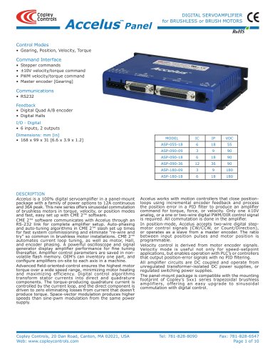 Accelus Panel
10 Pages
 Xenus XTL
30 Pages
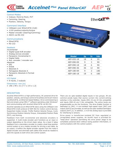 Accelnet Plus EtherCAT Panel
18 Pages
 Accelnet Micro Module and Kit
24 Pages
 Accelnet Module Development Kit
8 Pages
 Accelnet Module
14 Pages
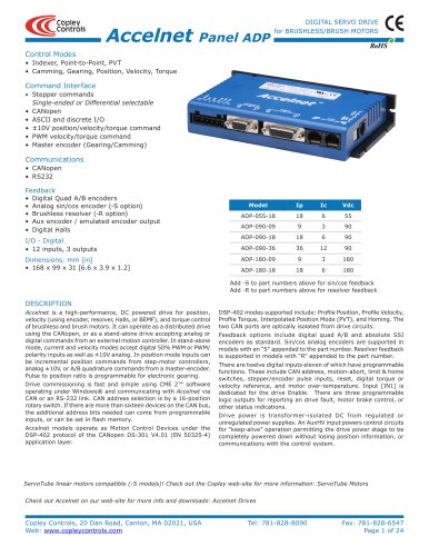 Accelnet Panel ADP
24 Pages





- Digital I/O
- Analog I/O
- Servo-amplifier
- Motor controller
- DC servo-amplifier
- Fieldbus servo-drive
- DC motor controller
- AC servo-amplifier
- Brushless servo-amplifier
- Stepper motor controller
- Communication interface card
- EtherCAT servo-amplifier
- Compact servo-amplifier
- CANopen servo-amplifier
- Digital servo-amplifier
- Stepper servo drive
- Industrial interface expansion card
- CANopen I/O
- Brushless motor control
- Digital input motor controller