Catalog excerpts
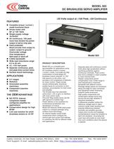
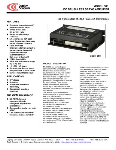
MODEL 503 DC BRUSHLESS SERVO AMPLIFIER ±50 Volts output at ±10A Peak, ±5A Continuous FEATURES Complete torque ( current ) mode functional block Drives motor with 60° or 120° Halls Single supply voltage 18-55VDC 5A continuous, 10A peak more than double the power output of servo chip sets Fault protected Short-circuits from output to output, output to ground Over/under voltage Over temperature Self-reset or latch-off 2.5kHz bandwidth Wide load inductance range 0.2 to 40 mH. +5, +15V Hall power Separate continuous, peak, and peak-time current limits Surface mount technology APPLICATIONS X-Y stages Robotics Automated assembly machinery Component insertion machines THE OEM ADVANTAGE NO POTS: Internal component header configures amplifier for applications Conservative design for high MTBF Low cost solution for small brushless motors to 1/3 HP Model 503 PRODUCT DESCRIPTION Model 503 is a complete pwm servoamplifier for applications using DC brushless motors in torque ( current ) mode. It provides six-step commutation of three-phase DC brushless motors using 60° or 120° Hall sensors on the motor, and provides a full complement of features for motor control. These include remote inhibit/enable, directional enable inputs for connection to limit switches, and protection for both motor and amplifier. The /Enable input has selectable active level ( +5V or gnd ) to interface with most control cards. /Pos and /Neg enable inputs use failsafe (ground to enable) logic. Power delivery is four-quadrant for bi-directional acceleration and deceleration of motors. Model 503 features 500W peak power output in a compact package using surface mount technology. An internal header socket holds components which configure the various gain and current limit settings to customize the 503 for different loads and applications. Separate peak and continuous current limits allow high acceleration without sacrificing protection against continuous overloads. Peak current time limit is settable to match amplifier to motor thermal limits. Header components permit compensation over a wide range of load inductances to maximize bandwidth with different motors. Package design places all connectors along one edge for easy connection and adjustment while minimizing footprint inside enclosures. High quality components and conservative ratings insure long service life and high reliability in industrial installations. A differential amplifier buffers the reference voltage input to reject common-mode noise resulting from potential differences between controller and amplifier grounds. Output short circuits and heatplate overtemperature cause the amplifier to latch into shutdown. Grounding the reset input will enable an auto-reset from such conditions when this feature is desired. Copley Controls, 20 Dan Road, Canton, MA 02021, USA Tel: 781-828-8090 Fax: 781-828-6547 Tech Support: E-mail: sales@copleycontrols.com, Web: http://www.copleycontrols.com
Open the catalog to page 1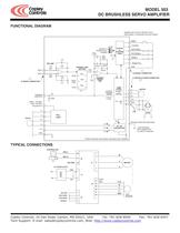
MODEL 503 DC BRUSHLESS SERVO AMPLIFIER FUNCTIONAL DIAGRAM MOMENTARY SWITCH RESETS FAULT WIRE RESET TO GROUND FOR SELF-RESET 3 SHORT/O.T. POWER FAULT NORMAL CH2 1.5 NF RH1 499K LED'S R R G +5V 8 STATUS & CONTROL LOGIC 4 5 6 1nF 7 REF AMP REF(-) 10 10K 10K RH7 CURRENT LIMIT SECTION 100K - 470 PF 2.2 MEG REF(+) 11 + RH6 10K RH3 PEAK 10K J2 SIGNAL CONNECTOR RH4 PEAK TIME 1nF 1 RESET +NORMAL NEG ENABLE POS ENABLE ENABLE ENABLE POL GND 100 PF J2 SIGNAL CONNECTOR + 50K CURRENT ERROR AMP J1 MOTOR & POWER CONNECTOR RH5 CONT Gv = 1 1K 33NF CURRENT 9 MONITOR OUTPUT CURRENT SENSE V HALLS W +5 +15 GND 1...
Open the catalog to page 2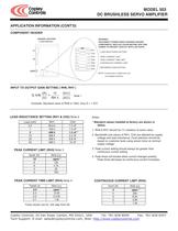
MODEL 503 DC BRUSHLESS SERVO AMPLIFIER APPLICATION INFORMATION (CONT'D) COMPONENT HEADER HEADER LOCATION WARNING! DISCONNECT POWER WHEN CHANGING HEADER COMPONENTS. REPLACE COVER BEFORE APPLYING POWER TO PREVENT CONTACT WITH LIVE PARTS. ( COVER REMOVED ) RH1 J1 LOAD INDUCTANCE SETTING CH2 RH3 PEAK CURRENT LIMIT RH4 PEAK CURRENT TIME LIMIT RH5 J2 CONTINUOUS CURRENT LIMIT RH6 REFERENCE GAIN SETTING RH7 LEDS NOTE: Components in dotted lines are not installed at factory INPUT TO OUTPUT GAIN SETTING ( RH6, RH7 ) G A IN (A) 10 = (V) RH 6 (k Ω ) (k Ω ) Note 1 Example: Standard value of RH6 is 10kΩ,...
Open the catalog to page 3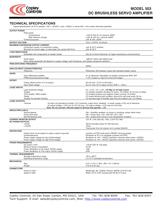
DC BRUSHLESS SERVO AMPLIFIER TECHNICAL SPECIFICATIONS Typical specifications @ 25°C ambient, +HV = +55VDC. Load = 200[jH. in series with 1 ohm unless otherwise specified. OUTPUT POWER Peak power After direction change _Continuous power_ OUTPUT VOLTAGE MAXIMUM CONTINUOUS OUTPUT CURRENT Convection cooled, no conductive cooling _Mounted on narrow edge, on steel plate, fan-cooled 400 ft/min LOAD INDUCTANCE _Selectable with components on header socket 200 uH to 40mH (Nominal, for higher inductances consult factory) Small signal -3dB @ 2.5kHz with 200[jH load Note: actual bandwidth will depend on...
Open the catalog to page 4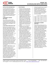
MODEL 503 DC BRUSHLESS SERVO AMPLIFIER APPLICATION INFORMATION SETUP BASICS To use the model 503 set up the internal header with the components that configure the transconductance, current limits, and load inductance. Current-limits and load inductance set up the amplifier for your particular motor, and the transconductance defines the amplifiers overall response in amps/volt that is required by your system. 1. Set RH1 and CH2 for motor load inductance (see following section). 2. Set RH3, 4, & 5 if current limits below standard values is required. 3. Ground the /Enable (/Enable Pol open),...
Open the catalog to page 5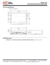
MODEL 503 DC BRUSHLESS SERVO AMPLIFIER OUTLINE DIMENSIONS Dimensions in inches (mm.) (19.1) 4.75 (120.7) (3.0) 0.75 0.17 3.27 (83.1) 2.00 (50.8) 4.50 (114.3) (14) 0.55 1.28 (32.5) ORDERING GUIDE Model 503 5A Continuous, 10A Peak, +18-55VDC Brushless Servoamplifier Copley Controls, 20 Dan Road, Canton, MA 02021, USA Tel: 781-828-8090 Fax: 781-828-6547 Tech Support: E-mail: sales@copleycontrols.com, Web: http://www.copleycontrols.com
Open the catalog to page 6All Copley Controls catalogs and technical brochures
-
XenusPLUS Compact EtherCAT XEC
30 Pages
-
XenusPLUS Compact CANopen XPC
30 Pages
-
Control Networks
8 Pages
-
R-Series Guide
8 Pages
-
Selection Guide
24 Pages
-
Xenus R10
30 Pages
-
Accelnet R23
24 Pages
-
Accelnet R22
22 Pages
-
Accelnet R21
24 Pages
-
Accelnet R20
24 Pages
-
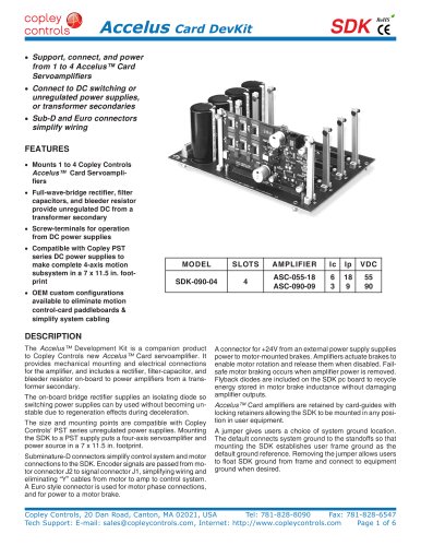
Accelus Card Development Kit
6 Pages
-
Accelus Card
8 Pages
-
ASP-X2 Accelus Panel Dual
10 Pages
-
Junus
10 Pages
-
CAN-PCI-02
2 Pages
-
CAN-IPM-01
8 Pages
-
Bantam
18 Pages
-
Bantam R30
18 Pages
-
Power Supply Subsystem
8 Pages
-
Shunt Regulator
2 Pages
-
Xenus PLUS 2-Axis CANopen
34 Pages
-
Xenus RoHS PLUS CANopen
28 Pages
-
Xenus PLUS 2-Axis EtherCAT
34 Pages
-
Xenus PLUS EtherCAT
28 Pages
-
Xenus Edge Filter
16 Pages
-
Regen Resistors
24 Pages
-
Xenus Micro
24 Pages
-
Accelus Card Development Kit
6 Pages
-
Accelus Card
8 Pages
-
Accelus Panel
10 Pages
-
Xenus XTL
30 Pages
-
Accelnet Plus EtherCAT Panel
18 Pages
-
Accelnet Micro Module and Kit
24 Pages
-
Accelnet Micro Panel
24 Pages
-
Accelnet Module Development Kit
8 Pages
-
Accelnet Module
14 Pages
-
Accelnet Panel ADP
24 Pages

