
- Catalogs
- Cooper Interconnect
- MIL-DTL-38999 Series III Filtered-Connectors

MIL-DTL-38999 Series III Filtered-Connectors

MIL-DTL-38999 Series III Filtered-Connectors
The MIL-DTL-38999 Series III filtered connectors are designed for high-density applications, offering configurations with shell sizes ranging from 9 to 25. They are built to withstand 500 mating cycles and operate in temperatures from -55°C to 125°C. The connectors feature quick mating, tri-start, self-locking couplings, and are available with platings that endure 500-hour salt-spray exposure. These connectors are suitable for EMI/RFI reduction in noise-sensitive applications such as avionics and communications.
Filter Performance
The connectors offer various filter types, including C, L, T, and Pi-type filters, which are optimized for specific frequency, voltage, and impedance requirements. The Pi filter provides superior high-frequency performance compared to the C filter due to its sharper roll-off.
Electrical Ratings and Capacitance Codes
The maximum operating voltage for Pi and C filters is 200VDC, with a current rating of at least 3.0 amps. The capacitance codes range from 53 pF to 18,000 pF, with attenuation minimums specified per MIL-STD-220.
Part Number Configuration
Part numbers are configured based on shell size, contact style, insert arrangements, class, shell type, series, polarization, termination type, filter type, and capacitance code.
Insert and Shell Arrangements
Various shell and insert arrangements are available, with specific service ratings and total contact numbers detailed in the document. Custom shells and inserts can be discussed with Cooper Interconnect.
Mechanical Drawings
Detailed mechanical drawings for box-mount and jam-nut configurations are provided, specifying dimensions and thread types for each shell size.
Insert and Contact Ratings
The document outlines suggested operating voltages and test voltages at various altitudes for different service ratings. Recommended contact ratings are provided for various wire sizes.
Polarization Tables
Polarization tables specify keyway ID letters and corresponding angular positions for different shell sizes.
For further customization and specifications, Cooper Interconnect can be contacted directly.
Catalog excerpts

MIL-DTL-38999 Series III Filtered Connectors
Open the catalog to page 1
in the Most Challenging Conditions Filter Performance Graphs 5 Electrical Ratings and Capacitance Codes 6 Part Number Configuration 7 Insert and Shell Arrangements 8 Insert and Contact Ratings 11 e-mail: [email protected]
Open the catalog to page 2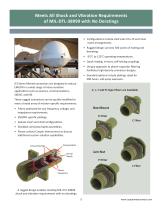
Meets All Shock and Vibration Requirements of MIL-DTL-38999 with No Deratings • Congurations include shell sizes 9 to 25 and most insert arrangements. • Rugged design survives 500 cycles of mating and demating. • -55°C to 125°C operating temperatures. • Quick mating, tri-start, self-locking couplings. • Unique approach to planar-capacitor ltering facilitates high-density-connector designs. • Standard options include platings rated for 500-hours, salt-spray exposure. G3-Series ltered connectors are designed to reduce EMI/RFI in a wide range of noise-sensitive applications such as avionics, communications,...
Open the catalog to page 3
Technical Specifications Materials, Finish, and Mechanical Class W Receptacle / Plug Shell and Coupling Ring Plating CRES (Passivated) Contact Material & Plating Copper Alloy with Gold plating, 50 micro-inches minimum Hard dielectric composite Grounding Springs Beryllium Copper Mating Life / Contact Retention 500 cycles minimum / up to 25 pounds Six keyways with optimal master keyway rotations. MIL-STD congurations include: N, A, B, C, D, and E Environmental, Shock, Vibration, and EMI/RFI Class W Operation Temperature Environmental Resistance Dust (ne sand) per MIL-STD-202 and ice resistance...
Open the catalog to page 4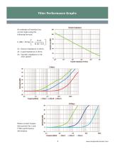
Filter Performance Graphs An estimate of insertion loss following formula: Zs = Source impedance in ohms Zl = Load impedance in ohms Transfer Impedance Transfer Impedance 2t Ohms FHterC —FlIterB —FllterA Please contact Cooper Frequency (MHi) Filter C —Filter B —FllterA
Open the catalog to page 5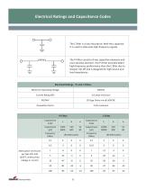
Electrical Ratings and Capacitance Codes The C lter is a low inductance, feed-thru capacitor. It is used to attenuate high-frequency signals. The Pi lter consists of two capacitive elements and one inductive element. The Pi Filter provides better high-frequency performance than the C lter due to sharper roll-o and is designed for high source and load impedances. Electrical Ratings - Pi and C Filters Maximum Operating Voltage Dissipation Factor Pi Filter Capacitance Code 0.5 Attenuation minimums per MIL-STD-220 @25oC without bias voltage or current Capacitance Code
Open the catalog to page 6
Part Number Configuration Cooper Interconnect Part Number Conguration G3 Series III Shell Type (table below) Capacitance Code (page 6) Class (table below) Filter Type (table below) Shell Size (Page 8) Termination Type (table below) Insert Arrangements (page 8) Contact Style (table below) Designator Descriptions Designator Type Termination Types Jam-Nut Mount CAD/OD per QQ-P-416 Nickel per ASTM B733 CRES (Passivated) Socket Capacitive Pi Filter, one capacitive and one inductive element One capacitive and one inductive element Filter Types Contact Style Finish Class Shell Type Cooper Inteconnect...
Open the catalog to page 7
Insert and Shell Arrangements The following tables list shell/insert arrangements that are available for ltered connectors. Please contact Cooper Interconnect to discuss custom shells and inserts. Shell Size Service Total # Rating Contacts Shell Size Insert Service Total # # Rating Contacts * Please contact factory for lead times.
Open the catalog to page 8
Box-Mount Mechanical Drawings Box Mount, Pi-Filter K-Thread SHELL SIzE
Open the catalog to page 9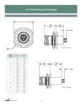
Jam-Nut Mechanical Drawings SHELL SIzE
Open the catalog to page 10
Insert and Contact Ratings Insert Service Ratings Suggested Operating Voltage (Sea Level) Test Voltage (Sea Level) Service Rating Recommended Contact Ratings (AMPS) Wire Size (AWG) Contact Size
Open the catalog to page 11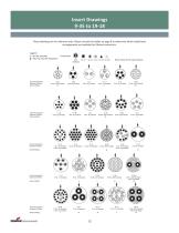
Insert Drawings These drawings are for reference only. Please consult the tables on page 8 to determine which shell/insert arrangements are available for filtered connectors. ■f = Not MIL-Standard Contact Size j = Main KeyH Key Way Polarization Insert Arrangement: Service Rating: No.8 No.io No.12 No.16 No.20No.22D [Front Face of Pin Insert Shown) Insert Arrangement: Service Rating; Insert Arrangement: Service Rating; Insert Arrangement: Service Rating: Insert Arrangement: Service Rating: COOPER Interconnect
Open the catalog to page 12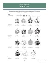
Insert Drawings These drawings are for reference only. Please consult the tables on page 8 to determine which shell/insert arrangements are available for filtered connectors. f = Not MIL-Standard Contact Size (Front Face of Pin Insert Shown) rvgert Arrangement: Service Rating: Insert Arrangement: Quantity arid Size: Service Hating: Insert Arrangement: Service Rating: Insert Arrangement: Service Rating:
Open the catalog to page 13
Insert Drawings These drawings are for reference only. Please consult the tables on page 8 to determine which shell/insert arrangements are available for filtered connectors. t = Not MIL-Standard Contact Size (Front Face of Pin Insert Shown) Insert Arrangement; Service Rating; Insert Anangement: Service Rating: Insert Arrangement; Service Rating; COOPER Interconnect
Open the catalog to page 14
Polarization Tables SHELL SIzE
Open the catalog to page 15
Customer Service Cooper Interconnect 750 West Ventura Blvd. Cooper Interconnect Aerospace & Military Connector Manufacturing Locations Cooper Interconnect 750 West Ventura Blvd. Cooper Interconnect Cooper Interconnect Cooper Interconnect Cooper Interconnect and the tradenames and brand names herein are valuable trademarks of Cooper Industries in the U.S. and other countries. Use of the Cooper Trademarks without the prior written consent of Cooper Industries is strictly prohibited. ©2012 Cooper Industries, pic. Reorder # CI-FBO612 COOPER Interconnect
Open the catalog to page 16All Cooper Interconnect catalogs and technical brochures
 WPI Resource Guide
38 Pages
 PC Connector Legacy Products
33 Pages
 Connectors and cables
68 Pages
 Class L Power Connectors
2 Pages
 Titan Ground Power
12 Pages
 55116 Audio Connectors
2 Pages
 SB Series
2 Pages
 55181 Dual entry connectors
2 Pages
 Right Angle Audio Connectors
2 Pages
 Extended Audio
2 Pages
 Stackable Power Connectors
2 Pages
 GPS Connectors
2 Pages
 ESP Oil & Gas Penetrators
2 Pages
 Aviation Ground Power Catalog
70 Pages
 MIL-DTL-38999 Series IV Catalog
56 Pages
 55181 Power Connectors Catalog
40 Pages


- Data connector
- Actuator
- Linear actuator
- Electric actuator
- Circular connector
- Single-pole switch
- Screw-in connector
- Rectangular connector
- Technology switch
- Cable assembly
- RF connector
- Electromechanical switch
- DIN connector
- Safety electric switch
- Multipole connector
- Crimp connector
- Watertight connector
- Locking connector
- Hermetic switch