
Catalog excerpts

HC7 Series HIGH CURRENT 7 Power Inductors Description RoHS 2002/95/EC • 155°C maximum total temperature operation • Surface mount inductors designed for higher speed switch mode applications requiring lower inductance, low voltage and high current • Design utilizes high temperature powder iron material with a non-organic binder to eliminate thermal aging • Inductance range from 0.22 uH to 4.81 uH • Current range from 35.8 to 9.8 Amps • Frequency range 1kHz to 500kHz Applications • Next generation microprocessors • High current DC-DC converters • VRM, multi-phase buck regulator • PC, Workstations, Routers • Telecom soft switches, Base Stations Environmental Data • Storage temperature range: -40°C to +155°C • Operating ambient temperature range: -40°C to +155°C (range is application specific) • Solder reflow temperature: +260°C max. for 10 seconds max. Part Number HC7-R20-R HC7-R47-R HC7-1R0-R HC7-1R5-R HC7-2R2-R HC7-3R9-R HC7-4R7-R 1) Test Parameters: 100KHz, 1.0Vrms 2) Irms Amperes for approximately ∆T of 40°C above 85°C ambient 3) Isat Amperes Peak for approximately 15% rolloff (@20°C) 4) Isat Amperes Peak for approximately 30% rolloff (@20°C) 5) Applied Volt-Time product (V-µS) across the inductor. This value represents the applied V-µS at operating frequency necessary to generate additional core loss which contributes to the 40°C temperature rise. De-rating of the Irms is required to prevent excessive temperature rise. The 100% V-uS rating is equivalent to a ripple current Ip-p of 20% of Isat (30% rolloff option). It is recommended that the temperature of the part not exceed 155°C under worst case operating conditions verified in the end application. Mechanical Diagrams Units supplied in tape and reel packaging. 13" reels 610 parts per reel. Carrier tape width = 24 mm. Meets EIA standard Part number definition: HC7-XXX-R HC7 = Product code and size XXX = Inductance value in uH. R = Decimal point. If no R is present, third character = #of zeros -R suffix indicates RoHS compliant SIDE VIEW wwllyy = Date code R = Revision level FRONT VIEW Packaging • Supplied in tape and reel packaging, 610 parts per reel Dimensions in Millimeters. All dimensions I+/- 0.2 mm unless otherwise specified. All soldering surfaces are coplanar within 0.15 mm.
Open the catalog to page 1
HC7 Series HIGH CURRENT 7 Power Inductors 4.0 Packaging Information SECTION A-A A0 User direction of feed Core Loss Irms DERATING WITH CORE LOSS % of Applied Volt-u-Seconds 20 % of Irms specified from zero ripple application Inductance Characteristics Inductance vs. Idc 5 4.5 4 HC7-R20 3.5 PM-4116 3/07 © Cooper Electronic Technologies 2007 Visit us on the Web at www.cooperbussmann.com 1225 Broken Sound Pkwy. Suite F Boca Raton, FL 33487 Tel: +1-561-998-4100 Toll Free: +1-888-414-2645 Fax: +1-561-241-6640 This bulletin is intended to present product design solutions and technical information...
Open the catalog to page 2All COOPER Bussmann catalogs and technical brochures
-
 Micro Blade Fuses
2 Pages
-
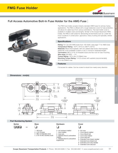 FMG Fuse Holder
1 Pages
-
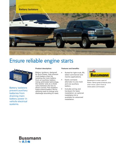 Battery Isolators
2 Pages
-
 True Sine Wave Inverter
2 Pages
-
 Converters / Equalizers
2 Pages
-
 Multi-Battery Isolators
4 Pages
-
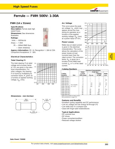 High Speed Fuses
2 Pages


Archived catalogs
-
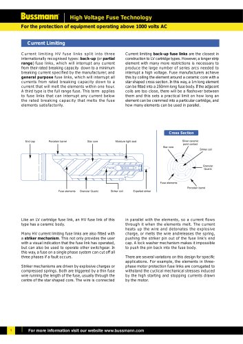 High Voltage
65 Pages
-
 Product Guide
6 Pages
-
 Full Line catalog
240 Pages