General catalog Glossary 16/17
1 /21Pages

General catalog Glossary 16/17
1 /21Pages
Catalog excerpts

glossary Highlights: ü Clearance ü Connectors ü Correction factors ü Degrees of protection ü EMC ü Excess gain ü Hysteresis ü Mounting ü Oil resistance ü Operating distance ü Parallel connection ü Switching frequency ü Tightening torque ü Turn-on/turn-off time
Open the catalog to page 1
inductive sensors photoelectric sensors adjustment (potentiometer) The sensitivity is adjusted by means of the built-in single or multi-turn potentiometer (if provided). Turning it clockwise increases the sensitivity. Multi-turn poentiometers t cannot be turned over their end position (no stops). Through-beam sensors / reflex sensors The potentiometer is normally set to the maximum sensitivity (turned clock ise). This w provides the maximum system reserve (excess-gain) sig al. n Diffuse sensors Set the sensitivity so that the target is reliably detected; for reliable operation, the green LED...
Open the catalog to page 2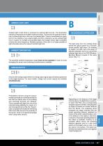
AMBIENT TEMPERATURE background suppression The specified ambient temperature range must not be exceeded in order to avoid damaging the sensor and rendering its perormance unreliable. f The light pulse from the emitting diode leaves the optical system as a focused, almost parallel, light beam. On meeting an object in its path, part of the beam is diffusely reflected, and in turn, part of this reflected light falls on the PSD (PositionSensitive Device) housed in the same sensor (Fig. 17). Ambient light is that which is produced by external light sources. The illumination intensity is measured...
Open the catalog to page 3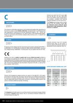
Sensors are sized from 0 3 up to M30 and C44 (40 mm x 40 mm). PNP, NPN and 2-wire AC/DC output configurations are available, combined with sensing distances between 0.6 mm and 40 mm. The Classics technology family includes devices from the following ranges: Basic, Miniature, Extra pressure, Extra temperature, High temperature, Weld-immune and Special. The maximum switchable capacitance is the greatest permissible total capacitance at the device’s output so that reliable switching is still guaranteed. Contributing to this total capacitance in particular are the lead capacitance (approx. 100 ......
Open the catalog to page 4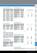
CLASSICS (SERIES 600, 620*) DIFFUSE SENSORS (FIG. 19) Size D reflex sensors (fig. 20) full inox (SERIES 700) Size D Photoelectric sensors must not mutually influence each other. For this reason, a minimum distance “a” between them has to be respected, which depends strongly on the model used and the actual sensit ivity setting. The following values should therefore be considered as rough guidelines only. The values given are for maximum sensitivity. diffuse sensors with background suppression through-beam sensors (FIG. 21) Series fiber-optic amplifiers The value “a” depends strongly on the specific...
Open the catalog to page 5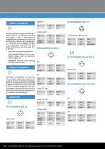
l» An innovative technology for producing inductive sensors. Contrary to conventional technology, in which a high-frequency magnetic field is generated in front of the sensing face, here the coil is triggered by an alternating polarity pulsed current. This technology is used in the Full Inox family (700 series) (see also page 20). It permits: 4501 Detailed data sheets for these products can be found on the Contrinex website:
Open the catalog to page 6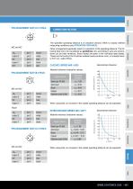
PIN ASSIGNMENT SIZE S12 5 POLE: When using foils, an increase in the usable operating distance can be expected. Inductive Photoelectric Ultrasonic Capacitive Safety RFID Connectivity Accessories ■ Glossary Index
Open the catalog to page 7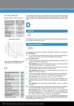
FULL INOX (SERIES 700) Material influence (indicative values): Target material Geometrical influence: The specified sensing ranges of energetic diffuse sensors are achieved using standard matt white paper of the specified dimensions as the target surface. For other target surface materials, the correction factors listed here apply (these are guideline values only). DARK-ON The “dark-ON” function means that the relevant output is switched (carrying current) when no light is reaching the receiver. When using foils, a decrease in the usable operating distance can be expected. DEGREES OF PROTECTION...
Open the catalog to page 8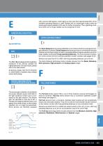
with a second LED (green), which lights up when less than approximately 80% of the available operating distance is used. Models with an excess-gain output make the excess-gain signal available to the user for further processing. Thus, operating conditions which are no longer reliable can be recognized in time. EMBEDDABLE MOUNTiNG D» See MOUNTING. EXTRA DiSTANCE FAMiLY D» EMC ::i D» The Extra Distance family (series 500/520) is one of three inductive sensing technologies offered by Contrinex. Extra Distance family sensors rely on conventional inductive oscillator and coil technology, but with...
Open the catalog to page 9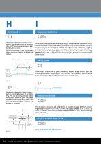
Hysteresis (differential travel) causes a defined switching be avior of the device h (Fig. 23). The sensing range always refers to the switch-on point. Distance hysteresis is only useful for the diffuse sensor model and its related fiber version. switch-on point switch-off point When inductive loads are switched off, the output voltage, without a protective circuit, would increase to a high value, which could destroy the output transistor. Contrinex sensors there ore contain a Zener diode at the output to limit the switch-off voltage to f a safe value (3-wire types). When connecting an inductive...
Open the catalog to page 10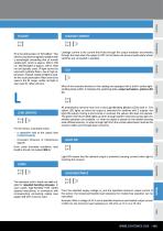
IR is the abbreviation of “Infra-Red”. This refers to any electromagnetic radiation with a wavelength exceeding that of normal visible light, which is approx. 380 to 780 nm. Wavelengths of approx. 780 to 1500 nm are typically used. IR light cannot be used with synthetic fibers, due to high attenuation. Instead, visible red light is used. As the usual polarization filters cannot be used in the IR range, visible red light is also used for reflex sensors. LEAD LENGTHS ::i D» For the sensor, long leads mean: - a capacitive load at the output (see CAPACITANCE) - increased influence of interference signals Even...
Open the catalog to page 11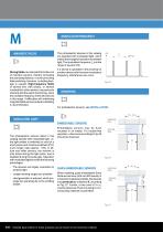
Strong fields can saturate the ferrite core of inductive sensors, thereby increasing the operating distance, or even provoking false switching. However, no lasting damage is caused. High-frequency fields of several kHz (700 series), or several hundred kHz (other series), may seriously interfere with the switch functioning, since the oscillator frequency of the devices lies in this range. If difi ulties with interfering fc magnetic fields are encountered, shielding is recommended. modulation frequency The photoelectric devices in this catalog are operated with modulated light, which makes them...
Open the catalog to page 12All CONTRINEX catalogs and technical brochures
 RFID Catalog
64 Pages
 Safety Catalog
48 Pages
 Program Overview
20 Pages
 General catalog Opto 16/17
135 Pages
 General Catalog 2016-2017
493 Pages
 General catalog Inductive 16/17
168 Pages
 General catalog Capacitive 16/17
32 Pages
 General catalog Safety 16/17
50 Pages
 General catalog RFID 16/17
63 Pages
 News catalog winter 16/17
28 Pages
 Inductive Extreme Flyer
2 Pages
 LTS-4050-101
3 Pages
 LTK-1180W-101
2 Pages
 LTK-1120-301
2 Pages
 LTK-1040-301
2 Pages


Archived catalogs
 Winter 2012 / 2013 NEWS
16 Pages
 Sensor-Tester
2 Pages
 Multi-beam synthetic fiber
2 Pages

- Data connector
- Rectangular housing
- Metal connector
- Proximity switch
- IP67 connector
- Metal housing
- Cylindrical proximity sensor
- Inductive proximity sensor
- Straight connector
- Cable connector
- IP67 proximity sensor
- Compact housing
- Nickel-plated brass connector
- Voltage connector
- Power distribution box
- Right-angle electrical connector
- DC proximity sensor
- Rectangular photoelectric sensor