High-precision analog I/O terminal for USB2.0 AIO-160802AY-USB
1 /4Pages

High-precision analog I/O terminal for USB2.0 AIO-160802AY-USB
1 /4Pages
Catalog excerpts

Ver.1.12 High-precision analog I/O terminal for USB2.0 AIO-160802AY-USB This product is a USB2.0 compatible terminal module that extends the analog I/O function of USB port of PCs. 8ch/16bits analog inputs and 2ch/16bits analog outputs are employed and signal lines can be directly connected to the screw terminals in the system. Compact design to match Note PCs and excellent in mobility as operation is powered by USB bus. This product accompanies Windows driver and full-fledged data logger software “C-LOGGER”. Possible to be used as a data recording device for MATLAB, with dedicated libraries. * Specifications, color and design of the products are subject to change without notice. Features Input 10μsec/ch, 8ch, output 10μsec, 2ch, 16bit resolution Equipped with the analog input (10μsec/ch, 16bit, 8ch), analog output (10μsec, 16bit, 2ch) and digital I/O (4ch each, LVTTL level) Compatible to USB1.1/USB2.0 and not necessary to power this product externally as the bus power is used. Compatible to USB1.1/USB2.0 and capable to achieve high speed transfer at HighSpeed (480 Mbps). Not necessary to power this product externally as the bus power of USB is used. Equipped with the buffer memory (1K data) which can be used in either FIFO or ring format This product includes buffer memory (1K data each for analog input and output) which can be used in either FIFO or ring format. You can perform analog I/O in the background, independent of software and the current status of the PC. Specification (1/2) Item Analog input Isolated specification Input type Number of input channels Input range Maximum input rating Input impedance Resolution Non-Linearity error Conversion speed Buffer memory Conversion start trigger Conversion stop trigger Specification Unisolated Single-Ended Input 8ch Bipolar ±10V ±20V 1MΩ or more 16bit ±12LSB 10μsec/ch (Max.) *3 1K data *8 Software / external trigger Number of sampling times / external trigger/software LVTTL level (Selecting one of the rising / falling / signal edge input to the DI00-pin by the software) LVTTL level (Selecting one of the rising / falling / signal edge input to External stop signal the DI01-pin by the software) External clock LVTTL level (Selecting the rising / falling to the DI02-pin by the signal software) Analog output Isolated Unisolated specification Number of output 2ch channels Output range Bipolar ±10V Absolute max. ±1mA output currency Output impedance 1Ω or less Resolution 16bit Non-Linearity error ±12LSB Conversion speed 10μsec (Max.) *3 Buffer memory 1K data Conversion start Software / external trigger trigger Conversion stop Number of sampling times / external trigger/software trigger LVTTL level (Selecting one of the rising / falling / signal edge input to External start signal the DI00-pin by the software) LVTTL level (Selecting one of the rising / falling / signal edge input to External stop signal the DI01-pin by the software) External clock LVTTL level (Selecting the rising / falling to the DI02-pin by the signal software) External start signal Windows compatible driver libraries are attached. Using the attached driver library API-USBP(WDM) makes it possible to create applications of Windows. In addition, a diagnostic program by which the operations of hardware can be checked is provided. Sampling can be driven by a clock or by various triggers Sampling can be started and stopped by software or by an external trigger (timing controlled by an externally input control signal). The sampling period can be controlled by the internal clock (high-precision timer included on the board) or by an external clock (externally input control signal). Terminal connector facilitating wiring Wiring is easy as the terminal connector (screw type) is used. Software-based calibration function Calibration of analog input/output can be all performed by software. Apart from the adjustment information prepared before shipment, additional adjustment information can be stored according to the use environment. AIO-160802AY-USB 1
Open the catalog to page 1
Ver.1.12 (2/2) Item Support Software Specification Digital I/O Number of input Unisolated input 4ch (LVTTL positive logic) *4*5 channels Number of output Unisolated output 4ch (LVTTL positive logic) channels USB Bus specification USB Specification 2.0/1.1 standard USB transfer rate 12Mbps (Full-speed), 480Mbps (High-speed) *6 Power supply Bus power Common section Connector 14 pin (screw-terminal) plug header Number of terminals 127 terminals (Max.) *7 used at the same time Power consumption 5VDC 450mA (Max.) Operating condition 0 - 50°C, 10 - 90%RH(No condensation) Physical dimensions 64(W) x...
Open the catalog to page 2
Ver.1.12 Block Diagram Using the On-terminal Connectors 8ch Single-end Analog Inputs 4 Digital Input / 4 Digital Output 2ch Analog Outputs CN2 CN1 OP Amplifer Multiplexer Buffer Connecting a terminal to a Connector To connect an external device to this terminal, plug the cable from the device into the interface connector (CN1, CN2) shown below. CN2 CN1 DA Converter OP Amplifer DC/DC converter FPGA A/D Converter Connector Pin Assignment USB 2.0 Controller & CPU CN2 CN1 14 13 12 11 10 9 8 7 6 5 4 3 2 1 USB Connector Physical Dimensions 62 AI00 - AI07 AO00 - AO01 AGND DI00 - Dl03 DO00 - DO03 DGND...
Open the catalog to page 3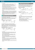
Ver.1.12 CAUTION If the signal source contains over 1MHz signals, the signal may effect the cross-talk noise between channels. If the product and the signal source receive noise or the distance between the product and the signal source is too long, data may not be input properly. An input analog signal should not exceed the maximum input voltage (relate to the product analog ground). If it exceeds the maximum voltage, the product may be damaged. Digital I/O signals Connection The digital I/O signal can be used .as the control signal (external trigger input signal and sampling clock input signal,...
Open the catalog to page 4All CONTEC catalogs and technical brochures
 BX-S3300
2 Pages
 FA Computer GPC-700 series
2 Pages
 Industrial Switching HUB
2 Pages
 IoT Products Line up
2 Pages
 General Product Catalog Ver.3.0
52 Pages
 CONPROSYS IO-Link Master
2 Pages
 CONPROSYS PAC series
7 Pages


- Lumibird panel PC
- Lumibird industrial panel PC
- Lumibird panel PC with touch screen
- Fanless panel PC
- Lumibird LCD panel PC
- Lumibird management software
- Lumibird automation software
- Lumibird industrial PC
- Lumibird Intel® Core™ PC
- Lumibird fanless PC
- IP65 panel PC
- Lumibird Intel® Core™ panel PC
- VESA mounting panel PC
- HDMI PC
- Lumibird embedded PC
- Lumibird box PC
- Lumibird RS-232 PC
- Lumibird Windows PC
- Lumibird USB 2.0 PC