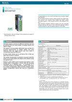
F&eIt series Isolated Analog Input Module ADI12-8(FIT)GY
1 /3Pages

F&eIt series Isolated Analog Input Module ADI12-8(FIT)GY
1 /3Pages
Catalog excerpts
Ver.1.00 F&eIt Series Isolated Analog Input Module ADI12-8(FIT)GY Congratulations on your recent purchase of an Insulator Digital Input Module. By converting external analog voltage signals into digital data, this product can process them inside the F&eIT series controller module < CPU-CAxx(FIT)GYGY, CPU-SBxx(FIT)GY etc >. The insulation between external signals and the Controller Module permits the use of the Controller Module without compromising the communications features of the latter. * Specifications, color and design of the products are subject to change without notice. Features The input range is common to different channels, and can be selected from four input ranges, including unipolar and bipolar ranges. Specification Specifications Item Specifications Analog input section The ability to accommodate differential input permits the accurate measurement of voltage values over long distances from the signal source and even under a considerable potential difference. Input format Bus-isolated voltage input Input range Bipolar ±10V, ±5V Maximum input voltage ±20V A rotary switch allows you to set device IDs to help you keep track of device numbers. Resolution 12-bit Non-linear error *1 ±3LSB Unipolar 0 - 10V, 0 - 5V Input impedance 1MΩ(Min.) Input channel Differential input, 8 channels Conversion rate The system incorporates a screwless connector plug that allows you to easily attach and detach wires without using any special tools. Similar to other F&eIT series products, the system, in the module itself, incorporates a 35-mm DIN rail mounting mechanism as a standard item. A connection to a controller module can be effected on a lateral, stack basis in a unique configuration, which permits a simple, smart system configuration without the need for a backplane board. Number of conversion channels x 10μsec + 20μsec Data buffer 8-Word Interrupt Either IRQ5 or IRQ7 or IRQ9 *2 Internal sampling timer 10μsec - 1,073,741,824μsec *3 Common section Internal power 5VDC±5% 350mA (Max.) consumption Maximum distance of 1.5m signal extension External dimensions (mm) 25.2 (W) x 64.7 (D) x 94.0 (H) (exclusive of protrusions) Weight (module itself) 100g Module connection method Stack connection by the connector that is provided with the side of module Module installation method One-touch connection to 35mm DIN rails (standard connection mechanism provided in the system) Applicable wire AWG 28 - 20 Applicable plug FK- MC 0,5/12-ST-2,5 (made by Phoenix Contact Corp.) *1 When the environment temperature is near 0ºC or 50ºC, the non-linearity error may become larger. *2 Available only when this product is connected to the CPU-SBxx(FIT)GY. *3 When this product is connected to the ADI12-8(USB)GY, the sampling timer built in the ADI12-8(USB)GY is used. The setting range is from 1,000 - 1,073,741,824μsec. CAUTION When connecting one of the modules to a controller module, the internal power consumption should be taken into account. If the total current exceeds the capacity of the power supply unit, the integrity of the operation cannot be guaranteed. For further details, please see the Controller Module manual. Depending upon the specific controller module that is used, some of the functions are not supported. ADI12-8(FIT)GY 1
Open the catalog to page 1
Ver.1.00 Installation Environment Requirements STATUS 3 4 5 RUN Device ID 6 0 1 Impact resistance When connecting the Module to an external device, you can use the supplied connector plug. When wiring the Module, strip off approximately 7 - 8 mm of the covering for the cable, and insert the bare wire by pressing the orange button on the connector plug. Releasing the orange button after the wire is inserted to fix the cable. Compatible wires are AWG 28 - 20. 7 Vibration Sweep resistance resistance How to Connect an Interface Connector Requirement description 0 - 50°C -10 - 60°C 10 - 90% RH (No...
Open the catalog to page 2
Ver.1.00 Setting a Device ID The controller module distinguishes and keeps track of the modules that are connected to it by assigning device IDs to them. Each module, therefore, should be assigned a unique ID. A Device ID can be assigned in a 0 - 7 range, so that a maximum of eight modules can be distinguished. To connect this product to the ADI12-8(USB)GY, assign a device ID between 1 and 3. The factory setting for the Device ID is [0]. Setup Method A device ID can be set by turning the rotary switch on the device face. To set a device ID, turn the switch knob. 6 3 01 45 7 Device ID Factory...
Open the catalog to page 3All CONTEC catalogs and technical brochures
 BX-S3300
2 Pages
 FA Computer GPC-700 series
2 Pages
 Industrial Switching HUB
2 Pages
 IoT Products Line up
2 Pages
 General Product Catalog Ver.3.0
52 Pages
 CONPROSYS IO-Link Master
2 Pages
 CONPROSYS PAC series
7 Pages


- Lumibird panel PC
- Lumibird industrial panel PC
- Lumibird panel PC with touch screen
- Fanless panel PC
- Lumibird LCD panel PC
- Lumibird management software
- Lumibird automation software
- Lumibird industrial PC
- Lumibird Intel® Core™ PC
- Lumibird fanless PC
- IP65 panel PC
- Intel® Core™ panel PC
- VESA mounting panel PC
- HDMI PC
- Embedded PC
- Lumibird box PC
- Lumibird RS-232 PC
- Lumibird digital I/O
- Lumibird Windows PC
- Lumibird USB 2.0 PC