- Catalogs
- CONEC Elektronische Bauelemente GmbH
- Part no. Creator
- Company
- Products
- Catalogs
- News & Trends
- Exhibitions
Part no. Creator
1 /2Pages

Part no. Creator
1 /2Pages
Catalog excerpts
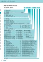
Part Number Creator for standard version Product Line 3 = Shell steel tin plated 1 = Brass tin plated* 5 = Shell yellow chromated* (not RoHS compliant) A = Stainless steel* Shell size and design 1 = 5W1, 2W2C 2 = 3W3, 7W2, 11W1, 3W3C 3 = 5W5, 9W4, 13W3, 17W2, 21W1 4 = 8W8, 13W6, 17W5, 21WA4, 25W3, 27W2 5 = 24W7, 36W4, 43W2, 47W1 Contact type P = Plug connector S = Socket connector Surface Quality class for signal contacts A = Quality class 3 = 50 mating cycles B = Quality class 2 = 200 mating cycles* C = Quality class 1 = 500 mating cycles J = Special application = > 500 mating cycles (on request)* X = Crimp and 3W3, 5W5, 8W8, 2W2C, 3W3C (no contacts are supplied with the connector) Termination only for signal contacts K = Crimp without contacts M = Solder cup N = Wire wrap, .500" 12.7 mm P = Press fit R = Solder pin, straight, .220" 5.6 mm T = Solder pin, angled, .280" 7.19 mm Termination for high power- or coaxial contacts Quality class 3 Quality class 1 C1 = Solder Crimp angled 10 A C2 = Solder Crimp angled 20 A C3 = Solder Crimp angled 30 A C4 = Solder Crimp angled 40 A F2,61 F1,41 = Solder cup 10 A F4,62 F3,42 = Solder cup 20 A F6,63 F5,43 = Solder cup 30 A F8,64 F7,44 = Solder cup 40 A 68 48 = Solder pin, straight 20 A, D= .077" 1.95 mm 69 49 = Solder pin, straight 20 A, D= .102" 2.60 mm 70 50 = Solder pin, straight 20 A, D= .110" 2.85 mm 71 51 = Solder pin, straight 30 A, D= .130" 3.18 mm 72 52 = Solder pin, straight 40 A, D= .150" 3.75 mm U = Solder pin, angled, .370" 9.40 mm W* = Solder pin, angled, .450" 11.43 mm X = 3W3, 5W5, 8W8, 2W2C, 3W3C Z* = Solder pin, angled, .540" 13.84 mm * = please contact us Quality class 3 Quality class 1 59 55 = Solder pin, angled 15 A 73 56 = Solder pin, angled 20 A 74 57 = Solder pin, angled 30 A 75 58 = Solder pin, angled 40 A 77 60 = Solder pin, angled 40 A 81 66 = Solder pin, angled 20 A 82 67 = Solder pin, angled 30 A 85 65 = Solder pin, angled 30 A G7 76 = 3 Solder pins Straight 50 Ω G9 78 = 3 Solder pins angled 50 Ω H1 79 = 3 Solder pins angled 50 Ω H4 80 = 5 Solder pins angled 50 Ω G8 86 = 3 Solder pins Straight 75 Ω Mounting style A1 = Riveted A2 = M3 threaded insert A3 = 4-40 UNC threaded insert A4 = M3 threaded rear spacer A5 = 4-40 UNC threaded rear spacer A6 = Float fastening A7 = Threaded rear spacer for M3 press fit A8 = Threaded rear spacer for 4-40 UNC press fit C1 = M3 threaded rear spacer with PCB clip, PCB .063" 1.60 mm C2 = 4-40 UNC threaded rear spacer with PCB clip, PCB .063" 1.60 mm C3 = M3 threaded rear spacer with PCB clip, PCB .091" 2.30 mm C4 = 4-40 UNC threaded rear spacer with PCB clip, PCB .091" 2.30 mm C5 = M3 threaded rear spacer with PCB clip, PCB .126" 3.20 mm C6 = 4-40 UNC Threaded rear spacer with PCB clip, PCB .126" 3.20 mm D1 = M3 clip and threaded rear spacer with PCB clip, PCB .063" 1.60 mm D2 = 4-40 UNC clip and threaded rear spacer with PCB clip, PCB .063" 1.60 mm D3 = M3 clip and threaded rear spacer with PCB clip, PCB .091" 2.30 mm D4 = 4-40 UNC clip and threaded rear spacer clip, PCB .091" 2.30 mm D5 = M3 clip and threaded rear spacer with PCB clip, PCB .126" 3.20 mm D6 = 4-40 UNC clip and threaded rear spacer with PCB clip, PCB .126" 3.20 mm E1 = M3 threaded rear spacer with PCB clip, PCB .063" 1.60 mm E2 = 4-40 UNC threaded rear spacer with PCB clip, PCB .063" 1.60 mm E3 = M3 threaded rear spacer with PCB clip, PCB .091" 2.30 mm E4 = 4-40 UNC threaded rear spacer with PCB clip, PCB .091" 2.30 mm E5 = M3 threaded rear spacer with PCB clip, PCB .126" 3.20 mm OX = Standard Quality class 3 Quality class 1 H2 88 = 3 Solder pins angled 75 Ω H3 89 = 3 Solder pins angled 75 Ω H5 90 = 5 Solder pins angled 75 Ω 91 = Screw termination 20 A P1 = press fit 30A P2 = press fit 30A P4 = press fit 30A 99 = no high power, coax or crimp contacts loaded Coaxial contacts with cable termination must be ordered separately. = 4-40 UNC threaded rear spacer with PCB clip, PCB .126" 3.20 mm = M3 clip and threaded rear spacer with PCB clip, PCB .063" 1.60 mm = 4-40 UNC clip and threaded rear spacer with PCB clip, PCB .063" 1.60 mm = M3 clip and threaded rear spacer with PCB clip, PCB .091" 2.30 mm = 4-40 UNC clip and threaded rear spacer with PCB clip, PCB .091" 2.30 mm = M3 clip and threaded rear spacer with PCB clip, PCB .126" 3.20 mm = 4-40 UNC clip and threaded rear spacer with PCB clip, PCB .126" 3.20 mm = Metal bracket, M3 threaded insert for .370" 9.40 mm = Metal bracket, 4-40 UNC threaded insert for .370" 9.40 mm = Metal bracket, M3 threaded insert and clip for .370" 9.40 mm = Metal bracket, 4-40 UNC threaded insert and clip for .370" 9.40 mm = Metal bracket, M3 threaded lock for .370" 9.40 mm = Metal bracket, 4-40 UNC threaded lock for .370" 9.40 mm = Metal bracket, M3 threaded lock and clip for .370" 9.40 mm = Metal bracket, 4-40 UNC threaded lock and clip for .370" 9.40 mm = Metal bracket, M3 threaded insert for .280" 7.19 mm = Metal bracket, 4-40 UNC threaded insert for .280" 7.19 mm = Metal bracket, M3 threaded insert and clip for .280" 7.19 mm = Metal bracket, 4-40 UNC threaded insert and clip for .280" 7.19 mm = Metal bracket, M3 threaded lock for .280" 7.19 mm = Metal bracket, 4-40 UNC threaded lock for .280" 7.19 mm = Metal bracket, M3 threaded lock and clip for .280" 7.19 mm = Metal bracket, 4-40 UNC threaded lock and clip for .280" 7.19 mm = Threaded rear spacer with M3 press in pin = Threaded rear spacer with 4-40
Open the catalog to page 1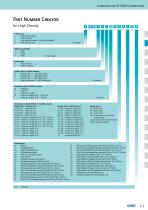
Part Number Creator for High Density Product Line 1 = Shell brass tin plated 3 = Shell tin plated* 5 = Shell yellow chromated* (not RoHS compliant) A = Shell stainless steel* Shell size and design 2 =19W1 3 =15W4 4 =45W2 Contact type P = Plug connector S = Socket connector Quality class for signal contacts A = Quality class 3 = 50 mating cycles B = Quality class 2 = 200 mating cycles* C = Quality class 1 = 500 mating cycles J = Special application = > 500 mating cycles* Termination only for signal contacts M = Solder cup P = Press-fit* R = Solder pin, straight W = Solder pin, angled .450" / 11,43...
Open the catalog to page 2All CONEC Elektronische Bauelemente GmbH catalogs and technical brochures
 CONEC SuperCon Hybrid Connectors
64 Pages
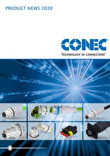
 Product News 2018
24 Pages
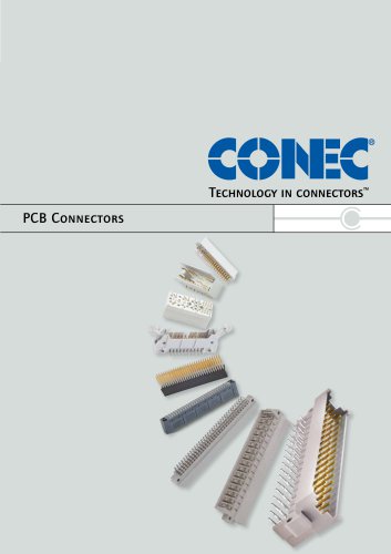 PCB connectors main catalogue
204 Pages
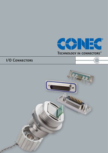 I/O connectors main catalogue
639 Pages
 Product News 2019
16 Pages
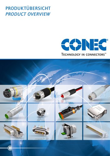 Product Overview
40 Pages
 D-SUB HD
1 Page
 D-SUB Combination
1 Page
 M12 BAYONET LOCKING
12 Pages
 IP67 D-SUB CONEC SlimCon
1 Page
 Overview Circular Connectors
2 Pages
 Valve Connectors
18 Pages
 CONEC Hybrid Overview
10 Pages
 M8x1 SMT/THR press release
2 Pages
 IP67 RJ45 overview
1 Page
 Junction systems overview
22 Pages
 Product overview hoods
1 Page
 CONE SnapLock connectors
1 Page
 PC104_PC104plus overview
1 Page
 Hybrid connectors
10 Pages
 Power Bajonett Presse
1 Page
 Power Bayonet overview
1 Page
 M12x1 Power overview
1 Page
 ISOBUS Connetors
2 Pages
 BUS-systems overview
1 Page
 HT overview
15 Pages
 CompactPCI overview
1 Page
 X-coded overmoulded
1 Page
 Overview Hybrid connectors 2023
10 Pages
 Hybrid overview 2023
10 Pages
 CONEC Hybrid Overview
8 Pages
 PCB connectors overview
7 Pages
 Industrial Ethernet connectors
15 Pages
 CONEC SnapLock Drawin
1 Page
 Product News SnapLock
1 Page
 SlimCon Filter Connectors
2 Pages
 Drawing
1 Page


Archived catalogs
 M8x1 SMT/THR overview
20 Pages
 Hybrid Overview
8 Pages


- Data connector
- Rectangular housing
- Electrical power supply connector
- Metal connector
- Round connector
- Polymer connector
- Socket electrical connector
- Screw-in connector
- Industrial connector
- Circular connector
- IP67 connector
- Rectangular connector
- Industrial housing
- Male connector
- Current connector
- Cable connector
- Electronic equipment enclosure
- Copper connector
- Custom housing