
- Catalogs
- CONEC Elektronische Bauelemente GmbH
- Junction systems overview


- Company
- Products
- Catalogs
- News & Trends
- Exhibitions
Junction systems overview

Junction systems overview
Overview of Junction Systems
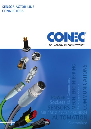
This document provides a detailed overview of various junction systems used in Sensor and Actor Line (SAL) applications, focusing on connectors such as Y-Splitters, DUO-Splitters, T-Splitters, and Adapters with installation sizes M8x1 and M12x1.
Nomenclature and Coding
The nomenclature for SAL junction systems is systematically structured to convey key product attributes:
- Gender: 'S' denotes male connectors, 'K' denotes female connectors.
- Number of Poles: Options include 2PE, 3, 4, 5, and 8 positions.
- Design Type: 'Y' for Y-Splitter, 'D' for DUO-Splitter, 'T' for T-Junction, 'R' for Circular connector.
- Coding: 'A-coding' applies to M12x1 connectors; standard coding for M8x1.
- Quantity: Number of input/output ports (e.g., 2).
- Installation Size: '8' for M8x1, '12' for M12x1.
- Configuration: Axial or angled (denoted by 'W').
- Cable Length and Quality: Length specified in meters; cable types include TPU (black, highly flexible, halogen-free, UL certified) identified as K1.
Product Specifications
- Materials: Contacts are copper-zinc (CuZn) with nickel and gold plating; contact carriers made from TPU GF or PA; overmoulds use TPU; sealing employs FPM; coupling nuts are GD-Zn or stainless steel.
- Electrical Ratings: Rated voltages range from 30 V to 250 V AC/DC depending on model; current ratings vary from 0.25 A up to 4 A; insulation resistance and pollution degree comply with IEC standards.
- Mechanical and Environmental Standards: Protection ratings from IP65 to IP67 per IEC 60529; mating cycles conform to IEC 60512-9a; recommended tightening torque is 0.4 Nm (SW 9) for M8 connectors and 0.6 Nm (SW 13) for M12 connectors.
Standards Compliance
Junction systems adhere to multiple IEC standards ensuring interoperability and safety:
- IEC 61076-2-101 and IEC 61076-2-104 for connector specifications.
- IEC 60512 series for mechanical and electrical testing.
- IEC 60664-1 for insulation coordination.
- IEC 60529 for ingress protection.
Product Variants and Part Numbers
The document includes detailed tables listing part numbers, contact assignments, rated voltages, current ratings, wire cross sections, cable lengths, and coding for various junction types:
- Y-Splitters: Male M8x1 or M12x1 connectors splitting into two female connectors; available in 3, 4, 5, and 8 pole versions.
- DUO-Splitters: Similar to Y-Splitters but designed for dual outputs; available in axial or angled configurations.
- T-Splitters/Adapters: T-shaped junctions with options for stainless steel coupling nuts; available for M8x1, M12x1, and 7/8" sizes; configurations include male and female connectors with various pole counts.
- Adapters: Male-to-female or male-to-male connectors for M12x1 junctions, including versions with stainless steel coupling nuts.
Key Technical Parameters
- Rated voltages range from 30 V to 250 V AC/DC depending on connector type and pole count.
- Current ratings vary from 0.25 A to 4 A; wire cross sections typically between 0.25 mm² and 0.34 mm².
- Cable materials include TPU (halogen-free, UL certified) and PVC (grey, LiYY).
- Configurations support both axial and angled cable exits to accommodate installation needs.
Installation and Handling Recommendations
- Recommended tightening torque: 0.4 Nm using SW 9 wrench for M8 connectors.
- Recommended tightening torque: 0.6 Nm using SW 13 wrench for M12 connectors.
- Products are designed for multiple mating cycles to ensure durability in industrial environments.
Connector M12x1 Overview
This section describes stainless steel coupling nuts and screws for M12x1 connectors, specifically type 321.
Technical Specifications Table
| Number of Poles Side A | Number of Poles Side B | Number of Poles Side C | Rated Voltage [V] | Current Rating [A] | Description | Part Number |
|---|---|---|---|---|---|---|
| 2+PE | 2+PE | 2+PE | 250 | 10 | SAL-7⁄8-TS2PE-TK2PE-TK2PE | 41-30001 |
| 4+PE | 4+PE | 4+PE | 250 | 10 | SAL-7⁄8-TS4PE-TK4PE-TK4PE | 41-30002 |
Additional Components
- 7/8" Junction boxes
- T-splitter
- Male connector 7/8"
- Two female connectors 7/8"
Notes
Further technical information is available on page 348.
Summary
This document comprehensively covers the design, specifications, coding, and ordering information for SAL junction systems including Y-Splitters, DUO-Splitters, T-Splitters, and adapters. It highlights compliance with international IEC standards, robust material selection, and detailed technical parameters to support reliable sensor and actor line connections in industrial automation environments.
Catalog excerpts
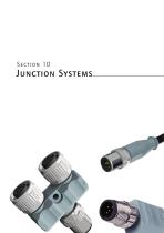
Junction Systems
Open the catalog to page 1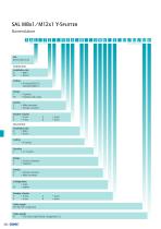
Til III II Hill —1| SAL Sensor Actor Line Connection Installation size 8 = M8x1 Coding = A-coding (M12x1) Standard (M8x1) Design Y = Y-Splitter YR = Y-Splitter with cable Gender S = Male connector Allocation Installation size 8 = M8x1 Design R = Circular connector Gender K = Female connector Configuration = axial W = angled Cable length XX/XX/XX= Length [m] Cable quality K1 = TPU, black, high flexible, halogenfree, UL
Open the catalog to page 3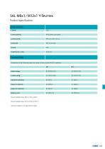
Basic material Contact plating Nickel plated, gold plated Contact carrier Coupling nut/-screw Technical Data Information on the following pages are basing on below mentioned IEC-standards. Rated voltage Current rating Insulation resistance Mating cycles Recommended torque M8: 0.4 Nm at SW 9 Recommended torque M12: 0.6 Nm at SW 13 Technical subject to change without notice.
Open the catalog to page 4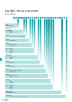
SAL Sensor Actor Line Connection Installation size 8 = M8x1 Coding = A-coding (M12x1), Standard (M8x1) Design D = DUO-Splitter Gender S = Male connector Allocation Installation size 8 = M8x1 Design R = Circular connector with cable Gender K = Female connector Building = Axial W = Angled Cable length XX/XX = Length [m] Cable quality K1 = TPU, black, high flexible, halogenfree, UL
Open the catalog to page 5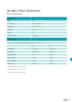
Basic material Contact plating Nickel plated, gold plated Coupling nut/-screw Cu-Zn, nickel plated Technical Data Information on the following pages are basing on below mentioned IEC-standards. Recommended torque M8: 0.4 Nm at SW 9 Recommended torque M12: 0.6 Nm at SW 13 Technical subject to change without notice.
Open the catalog to page 6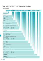
SAL Sensor Actor Line Connection '1| Coding = A-coding Design T = T-Junction Gender S = Male connector Design E = with stainless steel coupling nut/screw Design T = Circular connector Configuration K = Female connector Design E = with stainless steel coupling nut/screw Design R = Circular connector Gender K = Female connector Design E = with stainless steel coupling nut/screw Cable length XX = Length [m] Cable quality A1 = PVC, grey K1 = TPU, black, high flexible, halogenfree, UL
Open the catalog to page 7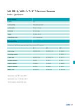
Basic material Contact plating Nickel plated, gold plated Contact carrier Coupling nut/-screw GD-Zn / Stainless steel Technical Data Information on the following pages are basing on below mentioned IEC-standards. Rated voltage Overvoltage category Current rating Mating cycles Recommended torque M8: 0.4 Nm at SW 9 Recommended torque M12: 0.6 Nm at SW 13 Technical subject to change without notice.
Open the catalog to page 8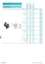
Number of poles Side C Contact assignment Male connector M8x1 2x Female connector M8x1 Number of poles Side B Number of poles Side A Technical information starting on page 348
Open the catalog to page 9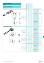
Wire cross section [mm2] Contact assignment Number of poles side C Male connector M12x1 axial 2x Female connector M12x1 axial Number of poles side B Number of poles side A Technical information starting on page 348
Open the catalog to page 10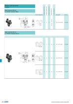
M12x1 Junction boxes Y-splitter 310 CONX® Technical information starting on page 348
Open the catalog to page 11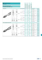
Wire cross section [mm2] Contact assignment Number of poles side C Male connector M8x1 axial 2 x Female connector M8x1 axial Number of poles side B Number of poles side A Technical information starting on page 348
Open the catalog to page 12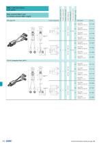
Wire cross section [mm2] Contact assignment Number of poles side C Male connector M8x1 axial 2 x Female connector M8x1 angled Number of poles side B Number of poles side A Technical information starting on page 348
Open the catalog to page 13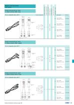
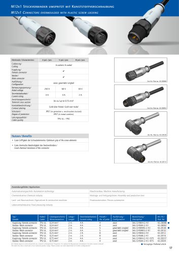
M12xl Junction boxes DUO-splitter Female connector M12x1 axial 2 x Male connector M8x1 axial ■SJ -SJ -SJ D D <J) -Q -Q -Q III TPU, UL, halogenfree, black, Li9Y11Y Contact assignment M. M. M. Female connector M12x1 axial 2 x Male connector M8x1 angled Female connector M12x1 axial 2 x Male connector M12x1 axial 03 SAL-12-DK4-8- 43 16276 Technical information starting on page 348
Open the catalog to page 14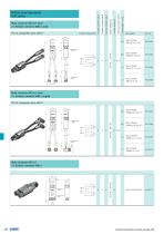
M12x1 Junction boxes DUO-splitter Contact assignment Male connector M12x1 2 x Female connector M8x1 SAL-12-DS4-8-2DK3 43-05117 Technical information starting on page 348
Open the catalog to page 15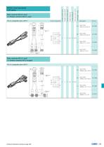
M12x1 Junction boxes DUO-splitter Contact assignment Technical information starting on page 348 CONSC® 315
Open the catalog to page 16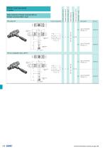
Wire cross section [mm2] Contact assignment Number of poles side C Male connector/Female connector M12x1 Female connector M8x1 axial Number of poles side B Number of poles side A Technical information starting on pag
Open the catalog to page 17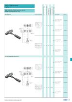
Wire cross section [mm2] Contact assignment Number of poles side C Male connector/Female connector M12x1 Female connector M12x1 axial Number of poles side B Number of poles side A Technical information starting on page 348
Open the catalog to page 18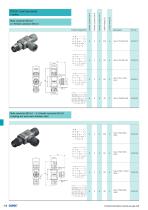
M12x1 Junction boxes T-splitter Male connector M12x1 2 x Female connector M12x1 JQ O Si Contact assignment Male connector M12x1 - 2 x Female connector M12x1 Coupling nut and screw stainless steel 4 250 318 CONX® Technical information starting on page 348
Open the catalog to page 19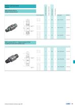
M12x1 Junction boxes Adapter Male connector M12x1 Female connector M12x1 Male connector M12x1 - Female connector M12x1 Coupling nut and screw stainless steel Contact assignment Description Part No. Technical information starting on page 348
Open the catalog to page 20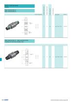
Contact assignment Male connector M12x1 Male connector M12x1 Number of poles Side B Number of poles Side A Male connector M12x1 – Male connector M12x1 Coupling nut and screw stainless steel Technical information starting on page 348
Open the catalog to page 21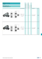
Technical information starting on page 348 Contact assignment Male connector 7/8" 2 x Female connector 7/8" Number of poles Side C Number of poles Side B Number of poles Side A
Open the catalog to page 22All CONEC Elektronische Bauelemente GmbH catalogs and technical brochures
 CONEC SuperCon Hybrid Connectors
64 Pages
 Product News 2018
24 Pages
 PCB connectors main catalogue
204 Pages
 I/O connectors main catalogue
639 Pages
 Product News 2019
16 Pages
 Product Overview
40 Pages
 D-SUB HD
1 Page
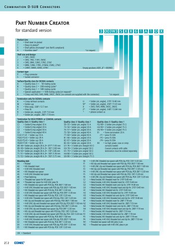 Part no. Creator
2 Pages
 D-SUB Combination
1 Page
 M12 BAYONET LOCKING
12 Pages
 IP67 D-SUB CONEC SlimCon
1 Page
 Overview Circular Connectors
2 Pages
 Valve Connectors
18 Pages
 CONEC Hybrid Overview
10 Pages
 M8x1 SMT/THR press release
2 Pages
 IP67 RJ45 overview
1 Page
 Product overview hoods
1 Page
 CONE SnapLock connectors
1 Page
 PC104_PC104plus overview
1 Page
 Hybrid connectors
10 Pages
 Power Bajonett Presse
1 Page
 Power Bayonet overview
1 Page
 M12x1 Power overview
1 Page
 ISOBUS Connetors
2 Pages
 BUS-systems overview
1 Page
 HT overview
15 Pages
 CompactPCI overview
1 Page
 X-coded overmoulded
1 Page
 Overview Hybrid connectors 2023
10 Pages
 Hybrid overview 2023
10 Pages
 CONEC Hybrid Overview
8 Pages
 PCB connectors overview
7 Pages
 Industrial Ethernet connectors
15 Pages
 CONEC SnapLock Drawin
1 Page
 Product News SnapLock
1 Page
 SlimCon Filter Connectors
2 Pages
 Drawing
1 Page





Archived catalogs
 M8x1 SMT/THR overview
20 Pages
 Hybrid Overview
8 Pages


