
- Catalogs
- Conductix-Wampfler
- Load Diagrams Program 0180 Cellular Buffers


- Company
- Products
- Catalogs
- News & Trends
- Exhibitions
Load Diagrams Program 0180 Cellular Buffers

Load Diagrams Program 0180 Cellular Buffers
- Energy per buffer is calculated using the formula: W = ½ m × v², where W is energy absorption in Joules, m is mass in kg, and v is velocity in m/s.
- Compression length and final load are determined from diagrams and tables.
- Verification criteria include ensuring S < 0.8 × h, F < Fmax, and a = v²/2s < amax, where S is travel, F is force, h is buffer height, and a is deceleration.
- Diagrams illustrate the relationship between work (KJ) and travel (mm) at different velocities (1 m/s to 4 m/s).
- Force (KN) versus travel (mm) is also depicted for static and dynamic conditions.
- Tables provide data on energy absorption and final load for various buffer sizes, such as 100x100, 80x40, 160x80, etc.
- Energy absorption and final load capacities are specified for different buffer dimensions.
- Graphs show how energy absorption and force change with travel distance and velocity.
Catalog excerpts

Load Diagrams Program 0180 Cellular Buffers
Open the catalog to page 1
Calculation Example 100 x 100 Energy absorption 90 80 Work [KJ] 100 x 100 Final load Force [KN] F 1. Calculation of energy per buffer: W = ½ m × v² 2. Readout compression length from the diagram 3. Readout final load of the buffer from the table 4. Result and verification ➞ S < 0,8 × h ➞ F < Fmax of the crane structure ➞ a = v²/2s < amax 2 W = Energy Absorption [J] s = Travel [mm] F = Force [kN] v = Velocity [m/s] m = Mass [kg] h = Buffer height a = deceleration
Open the catalog to page 2
© Conductix-Wampfler | 2015 | subject to technical modifications without prior notice has just one critical mission: To provide you with energy and data transmission systems that will keep your operations up and running 24/7/365. To contact your nearest sales office, please refer to: www.conductix.com/ contact-sear
Open the catalog to page 34All Conductix-Wampfler catalogs and technical brochures
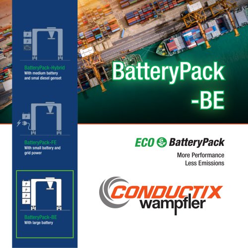 BatteryPack-BE
6 Pages
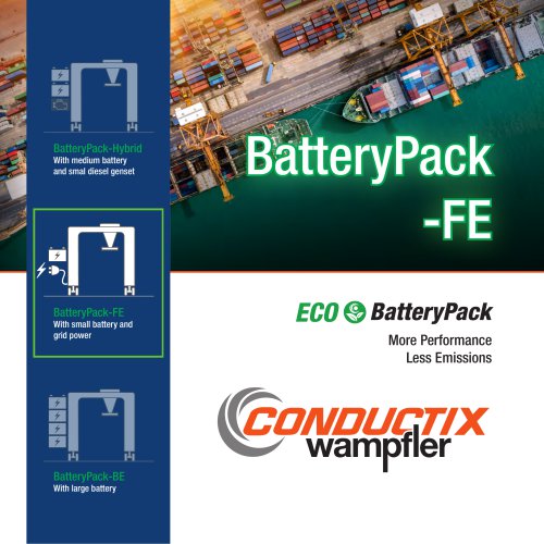 BatteryPack-FE
6 Pages
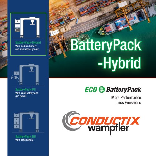 BatteryPack-Hybrid
6 Pages
 CGR Slip Rings
6 Pages
 WirelessCharger 3.0
20 Pages
 Jay RadioSafe
6 Pages
 Motor Driven Reels - MAG Drive
20 Pages
 Product Overview Motorized Reels
28 Pages
 Product Overview Conductor Rails
20 Pages
 Product Overview Cables
16 Pages







Archived catalogs
 Industrial Spring Reels
28 Pages
 Trailing Cable Reels
4 Pages
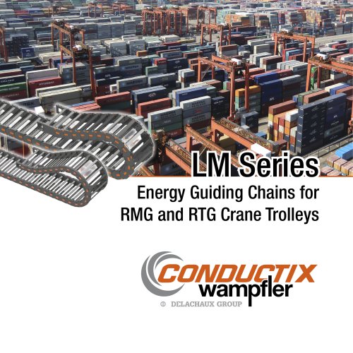 LM Series
6 Pages
 Festoon Systems for I-Beams
36 Pages
 Drive-In
4 Pages
 Jib Booms Program 0420
24 Pages
 Fiber optic Spring Reels
2 Pages








- Conductix slip ring
- Conductix fixed reel
- Conductix wireless remote control
- Conductix industrial remote control
- Conductix remote control with buttons
- Battery charger
- Hose reel
- Conductix spring-operated cable reel
- Metal slip ring
- Conductix cable reel
- Conductix IP65 remote control
- Jib crane
- Hollow-shaft electrical slip ring
- Electric electrical rotary joint
- Conductix metal reel
- Overhead traveling crane
- Conductix industrial slip ring
- Conductix crane remote control
- Compact electrical rotary joint
- Automatic battery charger