 Website:
Conductix-Wampfler
Group: Delachaux Group
Catalog excerpts

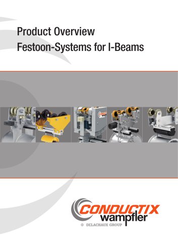
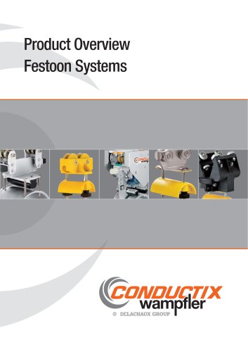
Festoon Systems for l-Beams
Open the catalog to page 1
Contents Festoon Systems Festoon System for Flat and Round Cables . . . . . . . . . . . . . . . . . . . . . . . . . . . . . . . . . . . . . . . . . . . . . . . . . . . . . . . . . . . . . . . . . . . . . . . . . . . . . . . . . . . . . . . . . . . . .4 Program 0350 with Main Rollers ø 50 and 63 mm Single Layer Cable Trolleys for Flat Cables with a Load Capacity up to 125 kg . . . . . . . . . . . . . . . . . . . . . . . . . . . . . . . . . . . . . . . . . . . . . . . . . . . . . . . . . . . . . . . . . . . .5 Selection of Cable Trolleys and Towing Trolleys . . . . . . . . . . . . . . . . . ....
Open the catalog to page 3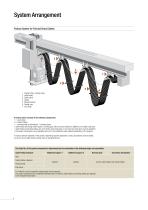
System Arrangement Festoon System for Flat and Round Cables Towing trolley / towing clamp Cable trolley Cable clamp Cables Damping device Towing rope End clamp A festoon sytem consists of the following components: • 1 x end clamp • X x cable trolleys • 1 x towing trolley or alternatively 1 x towing clamp • cable trolley and towing trolley require a running gear, which must be selected in addition to the trolley under part • cable trolleys and towing trolleys are set to fit the exact track beam, in all cases the track beam must be specified • the system components can be equipped with one or...
Open the catalog to page 4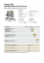
Program 0350 with Main Rollers ø 50 and 63 mm Single Layer Cable Trolleys for Flat Cables with a Load Capacity up to 125 kg Technical details Cable Supports Buffers Max. Travel Speed 1) Max. Load Capacity 1) Cable Trolley Underpart and Running Gear Fasteners Temperature Range 1) welded to the center plate, lateral-loading single-sided rectangular buffer 160 m/min 125 kg hot-dip galvanized steel stainless steel -30°C to + 80°C 1) depending on roller size/ roller material Ordering Example Clamping bar version 1 (continuous) Clamping bar version 2 (divided) A cable trolley underpart with the...
Open the catalog to page 5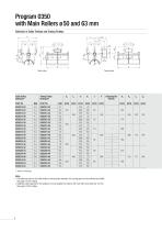
Program 0350 with Main Rollers ø 50 and 63 mm Selection of Cable Trolleys and Towing Trolleys lW Cable trolley Towing trolley 1) without running gear Notes • The table only refers to the cable trolley or towing trolley underpart, the running gear must be selected and added. See page 8 of this catalog. • Additional cable supports for this program are only available for systems with main roller sizes ø 80 and 100 mm. See page 9 of this catalog.
Open the catalog to page 6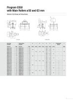
Program 0350 with Main Rollers ø 50 and 63 mm 90 Selection of End Clamps and Towing Clamps Towing clamp Towing Clamp Complete
Open the catalog to page 7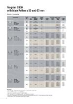
Program 0350 with Main Rollers ø 50 and 63 mm Selection of Running Gear Running Gear Main Roller Material Bandage Type HFG with cylindrical main rollers, horizontal guide rollers and anti-lift rollers Steel Polyurethane Steel Polyurethane Steel Polyurethane Steel Polyurethane Type HF with cylindrical main rollers and horizontal guide rollers Type HG with cylindrical main rollers and anti-lift rollers Type H with cylindrical main rollers Note/design • The running gear of the towing trolley must always be equipped with anti-lift rollers. • The anti-lift rollers ø 40 mm are made of steel. •...
Open the catalog to page 8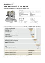
Program 0350 with Main Rollers ø 80 and 100 mm Single or Dual Layer Cable Trolleys for Flat Cables with a Load Capacity up to 350 kg Technical details Cable Supports Buffers Max. Travel Speed 1) Max. Load Capacity 1) Cable Trolley Underpart and Running Gear Fasteners Temperature Range 1) welded to the center plate, lateral-loading single-sided rectangular buffer 160 m/min 350 kg hot-dip galvanized steel stainless steel -30°C to + 80°C 1) depending on roller size/ roller material Ordering Example Clamping bar version 1 (continuous) Clamping bar version 2 (divided) A cable trolley underpart...
Open the catalog to page 9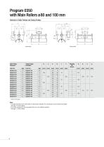
Program 0350 with Main Rollers ø 80 and 100 mm Selection of Cable Trolleys and Towing Trolleys lW Cable trolley Towing trolley 1) without running gear Notes • The table only refers to the cable trolley or towing trolley underpart, the running gear must be selected and added. See page 12 of this catalog. • The system components can be equipped with one or two additional supports. See page 11 of this catalog.
Open the catalog to page 10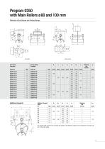
Program 0350 with Main Rollers ø 80 and 100 mm lk Selection of End Clamps and Towing Clamps Towing clamp Towing Clamp Complete Additional Supports Additional Support Order No. [kg] The support width as well as the clamping bar design of the additional support must correspond to the upper support of the cable trolley.
Open the catalog to page 11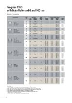
Program 0350 with Main Rollers ø 80 and 100 mm Selection of Running Gear Running Gear Main Roller Material Bandage Type HFG with cylindrical main rollers, horizontal guide rollers and anti-lift rollers Type HF with cylindrical main rollers and horizontal guide rollers Type HG with cylindrical main rollers and anti-lift rollers Type H with cylindrical main rollers Note/design • The running gear of the towing trolley must always be equipped with anti-lift rollers. • Main roller ø 80 mm: anti-lift rollers ø 50 mm and horiziontal guide rollers ø 50 mm made of steel • Main roller ø 100 mm:...
Open the catalog to page 12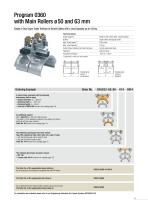
Program 0360 with Main Rollers ø 50 and 63 mm Single or Dual Layer Cable Trolleys for Round Cables with a Load Capacity up to 125 kg Technical details Cable Supports Buffers Max. Travel Speed 1) Max. Load Capacity 1) Cable Trolley Underpart and Running Gear Fasteners Temperature Range 1) bolted to the center plate, lateral-loading single-sided rectangular buffer 160 m/min 125 kg hot-dip galvanized steel stainless steel -30°C to + 80°C 1) depending on roller size/ roller material Ordering Example Clamping bar version 1 (continuous) Clamping bar version 2 (divided) A cable trolley underpart...
Open the catalog to page 13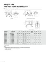
Program 0360 with Main Rollers ø 50 and 63 mm Selection of Cable Trolleys and Towing Trolleys lw Cable trolley 1) without running gear Notes The table only refers to the cable trolley or towing trolley underpart, the running gear must be selected and added. See page 16 of this catalog. • The system components can be equipped with an additional support. See page 15 of this catalog. •
Open the catalog to page 14All Conductix-Wampfler catalogs and technical brochures
-
CGR Slip Rings
6 Pages
-
WirelessCharger 3.0
20 Pages
-
Jay RadioSafe
6 Pages
-
Product Overview Motorized Reels
28 Pages
-
Product Overview Conductor Rails
20 Pages
-
Product Overview Cables
16 Pages
-
Motor Driven Reels - MAG Drive
20 Pages
-
Industrial Spring Reels
28 Pages
-
Trailing Cable Reels
4 Pages
-
LM Series
6 Pages
-
Drive-In
4 Pages
-
Jib Booms Program 0420
24 Pages
-
Fiber optic Spring Reels
2 Pages


