 Website:
Conductix-Wampfler
Group: Delachaux Group
Catalog excerpts

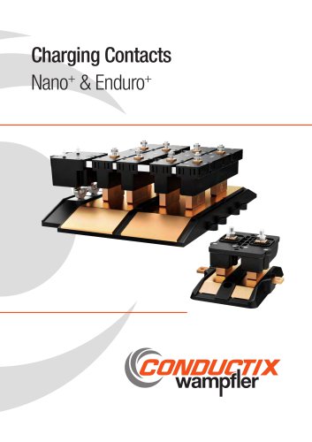
Charging Contacts Nano+ & Enduro+
Open the catalog to page 1
Robust design for high charging cycles The Nano+ and Enduro+ product lines are compact and modular charging contacts for use with different load conditions or performance parameters of mobile consumers, such as AGVs, mobile robots, AMRs, industrial vehicles, forklifts, pallet shuttles or other mobile units with energy storage. For the optimal use of individual vehicles or fleets, the selection of the storage system and the required charging infrastructure play an important role in order to be able to operate the systems as efficiently as possible in terms of payload, range, service life and...
Open the catalog to page 2
General Notes We reserve the right to make changes to the product at any time in the course of technical progress without prior notice. All our devices are CE-compliant. Our general terms and conditions apply. We will be happy to send you these on request. Reprinting, even in part, is only permitted with our permission.
Open the catalog to page 3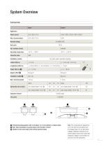
System Overview Technical Data Nano+ Rated current Nominal voltage Duty cycle Operating temperature Protection class Installation position any (floor, wall or overhead mounting) Spring force per contact Inspection interval Life cycles 1 Preload/mounting position with 4 mm (Nano+) or 18 mm (Enduro+) contact stroke 2 Max. lateral inclination or ground slope in the direction of travel 3 Distance to the lower edge of the vehicle (nominal value) Note: The components are designed for use in the extra-low and safety extralow voltage range. For use with higher voltages, additional measures for...
Open the catalog to page 5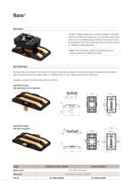
Nano+ Description The Nano+ charging contact series is specially designed for serial applications in the rated current range up to 75 A and a high number of load cycles and can be integrated easily and flexibly. The components meet the requirements of UL 583 and have been tested in endurance tests up to 1,000,000 (1 million) load cycles. Note: As with all charging contacts, the charging plate or the charging contacts can be fitted to the vehicle. Base Plate Nano+ The base plates are chamfered on both sides in the direction of travel and are available in two connection variants. Connection...
Open the catalog to page 6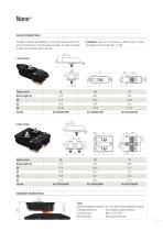
Nano+ Current Collector Nano+ Installation: using 2 x 5 mm screws, e.g. DIN 912 (max. 1.2 Nm) Connection bolt for nut M6 (max. 5.7 Nm) The Nano + contacts are available as 1 and 2-pole versions with 25, 50 and 75 A rated current. They are surface-mounted. The cable connection is made via a connection bolt on the rear. Rated current Rated current Installation situation Nano+ Note: Nominal installation dimension: Connection/fastening: Connection lug: Mounting plate: 48.1 mm with nominal preload of the spring (not included in scope of delivery) M6 x 1.0 (5.7 Nm) M5 cylinder head screw 7
Open the catalog to page 7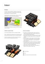
Enduro+ Description The Enduro+ series was developed for applications with higher rated currents from 100 to 600 A. The modular design of the system allows flexible integration into the respective application. Typical applications include industrial vehicles, transfer cars, mobile racking systems, amusement rides and similar applications. For entry and exit, the contacts are available with a ramp on one side or ramps on both sides. Flexibility in charging technology The wide range of applications requires a high degree of flexibility. •D ual length of the charging base plates for higher...
Open the catalog to page 8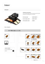
Enduro+ Configuration Configuration example Enduro+ 100 A, 2-pole with auxiliary contact and chamfered edge on both sides (connection of the charging plate on the underside) Part No. Base plate: Part No. Charging contact: Part No. Auxiliary contact: Cannot be combined D or S with W | P0 | P1 | P2 R with T P1 = 1 pair AUX contacts P2 = 2 pair AUX contacts
Open the catalog to page 9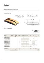
Enduro+ Preferred configurations for base plates | 2-pole Base plate Enduro+ 2-pole 252 Part No.: XA-MCB 100SBT-P0 H L B Chamfered edge
Open the catalog to page 10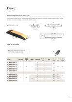
Enduro+ Preferred configurations for base plates | 1-pole If larger distances between the poles, individual positioning or a spatially offset arrangement are required, individual contacts are used. The rated current can be increased accordingly by connecting the contacts in parallel. Base plate Enduro+ 1-pole Note: The “SP” (Single Pole) in the order code addition indicates the single-pole version Chamfered edge XA-MCB SP200LBT-P0 XA-MCB SP200WBT-P0 XA-MCB SP200WST-P0 XA-MCB SP200WRE-P0
Open the catalog to page 11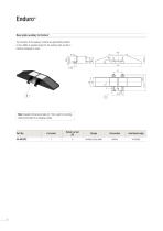
Enduro+ Base plate auxiliary for Enduro+ The contacts of the auxiliary contacts are galvanically isolated in the middle (2 separate poles) for the auxiliary pick-up with 2 contacts arranged in series. 86 32,3 Note: Supplied with pressure plate (X). This is used for mounting without connection to a charging contact. chamfered edge Auxiliary base plate
Open the catalog to page 12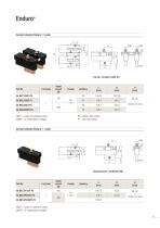
Enduro+ Current collector Enduro+ | 2-pole 5 P0 = without AUX contact P1 = with AUX contact 200LT = 2 pairs of contacts in series 200WT = 2 contact pairs in parallel Current collector Enduro+ | 1-pole 200LT = 2 pairs of contacts in series 200WT = 2 contact pairs in
Open the catalog to page 13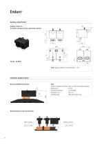
Enduro+ Auxiliary contact Enduro+ Auxiliary contact 5 A (2 contacts arranged in series, galvanically isolated) Note: Tightening torque for connecting bolt: 1,1 Nm Installation situation Enduro+ Nominal installation dimensions Note: Nominal installation dimension: Spring travel: Connection/fastening: Connection lug: Fastening plate: 89.4 mm with nominal spring preload 20 mm (not included) M6 x 1.0 M6 cylinder head screw Nominal distances (mean spring travel) Power contacts Auxiliary contacts
Open the catalog to page 14
Your Applications – our Solutions The solutions we deliver for your applications are based on your specific requirements. In many cases, a combination of several different Conductix-Wampfler systems can prove advantageous. You can count on Conductix-Wampfler for hands-on engineering support together with the optimum solution to safely meet your needs. Cable and Hose Reels Motor driven and spring driven reels by Conductix-Wampfler provide energy, data and media over a variety of distances, in all directions, fast and safe. Festoon Systems Conductix-Wampfler cable trolleys can be used in...
Open the catalog to page 15All Conductix-Wampfler catalogs and technical brochures
-
CGR Slip Rings
6 Pages
-
WirelessCharger 3.0
20 Pages
-
Jay RadioSafe
6 Pages
-
Product Overview Motorized Reels
28 Pages
-
Product Overview Conductor Rails
20 Pages
-
Product Overview Cables
16 Pages
-
Motor Driven Reels - MAG Drive
20 Pages
-
Industrial Spring Reels
28 Pages
-
Trailing Cable Reels
4 Pages
-
Festoon Systems for I-Beams
36 Pages
-
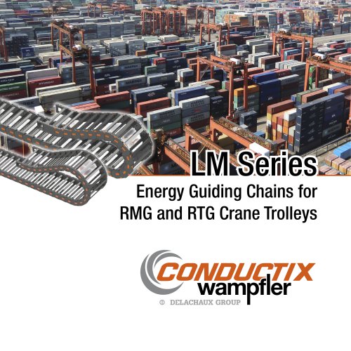
LM Series
6 Pages
-
Drive-In
4 Pages
-
Jib Booms Program 0420
24 Pages
-
Fiber optic Spring Reels
2 Pages

