 Website:
Conductix-Wampfler
Group: Delachaux Group
Catalog excerpts

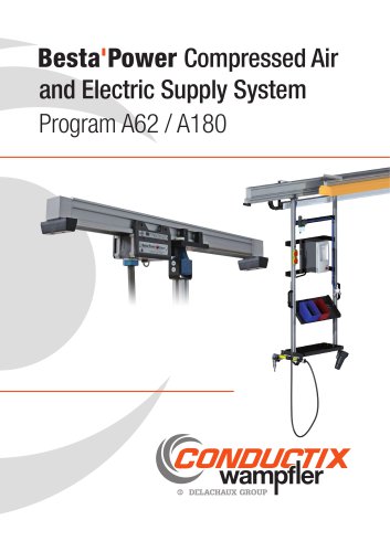
Besta Power Compressed Air and Electric Supply System Program A62 / A180
Open the catalog to page 1
Contents Rail Components 4 Rail Sections A62. . . . . . . . . . . . . . . . . . . . . . . . . . . . . . . . . . . . . . . . . . . . . . . . . . . . . . . . . . . . . . . . . . . . . . . . . . . . . . . . . . . . . . 4 Rail Sections A180. . . . . . . . . . . . . . . . . . . . . . . . . . . . . . . . . . . . . . . . . . . . . . . . . . . . . . . . . . . . . . . . . . . . . . . . . . . . . . . . . . . . . 6 Accessories A62 / A180. . . . . . . . . . . . . . . . . . . . . . . . . . . . . . . . . . . . . . . . . . . . . . . . . . . . . . . . . . . . . . . . . . . . . . . . . . . . . . . . . 8...
Open the catalog to page 3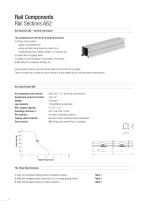
Rail Components Rail Sections A62 Rail Sections A62 - General Information The compressed air rail has the following functions: a) Energy carrier system: - supply of compressed air - energy and data transmission by means of an energy guiding chain, festoon system, or conductor rail b) Attachment for tapping valves c) Support for tool transporters, tool holders, and trolleys d) Mounting for accessories, lighting, etc Using connector pieces, the rails can be linked to form tracks of any length They are made from a hollow aluminum section and are suitable for dry and lubricated compressed air....
Open the catalog to page 4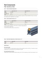
Rail Components Rail Sections A62 Table 1 - Rails with Integrated Tapping Valves Special Versions Non-standard lengths The rails are available in non-standard lengths according to customer specification . Length: max . 6000 mm .The position and number of tapping valves or connection plates have to be specified by the customer. Non-standard tapping valve spacing Available based on customer specification . Minimum spacing: 250 mm .At the rail's beginning: one-sided, minimum spacing: 125 mm .
Open the catalog to page 5
The compressed air rail has the following functions: a) Energy carrier system: - supply of compressed air - energy and data transmission by means of an energy guiding chain, festoon system, or conductor rail b) Attachment for tapping valves c) Support for tool transporters, tool holders, and trolleys d) Mounting for accessories, lighting, etc Using connector pieces, the rails can be linked to form tracks of any length They are made from a hollow aluminum section and are suitable for dry and lubricated compressed air. Additional elements, such as energy supplies, conductor rails, as well as...
Open the catalog to page 6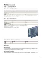
Rail Components Rail Sections A180 Table 1 - Rails with Integrated Tapping Valves Special Versions Non-standard lengths The rails are available in non-standard lengths according to customer specification . Length: max . 6000 mm .The position and number of tapping valves or connection plates have to be specified by the customer. Non-standard tapping valve spacing Available based on customer specification . Minimum spacing: 250 mm .At the rail's beginning: one-sided, minimum spacing: 125 mm .
Open the catalog to page 7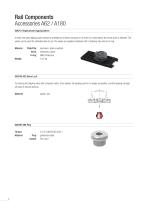
At least one spare tapping valve should be available at all times, because in the event of a valve failure the whole track is affected . The valves can be used for lubricated and dry air. The valves are supplied complete with 2 retaining clips and an O-ring . Plate/Clip: aluminum, black anodized Valve: elastomer, plastic O-ring: NBR (Perbunan) For locking the tapping valve with a bayonet catch . Once locked, the tapping point is no longer accessible, and the tapping carriage will pass it without docking. 048790-006 PlugThread: Material Plug: Gasket: G 1/2" DIN EN ISO 228-1...
Open the catalog to page 8
Rail Components Rail Connections A62 / A180 Rail Connections – General Information The rail connections serve as coupling elements for rail sections, types A62 and A180. They are screwed directly to the rail section and sealed with O-rings. All coupling types are interchangeable and can be passed by tapping and tool carriages, tool transporters, etc. The length of the connector types has no influence on the overall length of the installation. Only the lengths of the rail sections themselves are to be considered. If the Inlet Connector A62 with Vertical Connection G1" is used, the overall...
Open the catalog to page 9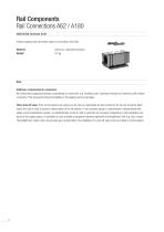
Rail Components Rail Connections A62 / A180 048810 Rail Connector A180 Simple coupling with connection plate for connecting A180 rails. Material: Weight: aluminum, colourless anodized 0.5 kg Note Stationary compressed air consumers We recommend supplying stationary compressed air consumers (e.g. handling units, machines) through rail connectors with vertical connection. This will avoid limiting the flexibility of the tapping and tool carriages. Filter, shut-off valve: If the rail connectors are used as an air inlet, an appropriate air filter (minimum 30-40 µm) should be fitted before the...
Open the catalog to page 10
The end pieces serve as rail termination or as axial air inlet . They are screwed to the face of the rail section and sealed with O-rings Each end piece is supplied with a rail end stop as limit stop for tapping and tool carriages, work stations, etc . Connection thread: Sealing face, connection thread: Material Termination: G 1 1/4" DIN EN ISO 228-1 flat seals, DIN 3852 aluminum, colourless anodized elastomer, NBR (Perbunan) 0.4 kg Axial air inlet: Connection pieces must either have a parallel pipe thread (ISO 228-1) with a flat seal or a taper thread (ISO 7-1) .Taper threads must be...
Open the catalog to page 11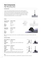
Rail Components Rail Mounting A62 Rail Mounting A62 In order to allow linear thermal expansion of the aluminum rails, two different hangers are available. The fixed point hanger (red) must only be used once per track, preferably next to the inlet. It fixes the rail in all three planes. The sliding hanger (black) is used for all other suspension points and allows linear expansion of the track. Depending on the attached load, the spacing between the suspension points is approx. 2 to 3 m (see p. 4). Whenever possible, one hanger should always be positioned close (max. 0.4 m) to the rail...
Open the catalog to page 12
Rail Components Rail Mounting A62 Positioning of Fixed Point Hanger 200 - 400 For each rail track only one fixed point hanger (red) type 048720-F-M10RH or 048720-F-M10LH is required. The fixed point hanger should always be positioned close to an air inlet (e.g. axial air inlet type 048730-06 or inlet coupling type 048731-05). Whenever possible, one hanger should always be positioned close (max. 0.4 m) to the rail connector. Spacing between Hangers Installations without work stations, tool holders, etc., max. spacing 3400 mm 200 - 400 Installations with work stations, tool holders, etc.,...
Open the catalog to page 13All Conductix-Wampfler catalogs and technical brochures
-
CGR Slip Rings
6 Pages
-
WirelessCharger 3.0
20 Pages
-
Jay RadioSafe
6 Pages
-
Product Overview Motorized Reels
28 Pages
-
Product Overview Conductor Rails
20 Pages
-
Product Overview Cables
16 Pages
-
Motor Driven Reels - MAG Drive
20 Pages
-
Industrial Spring Reels
28 Pages
-
Trailing Cable Reels
4 Pages
-
Festoon Systems for I-Beams
36 Pages
-
LM Series
6 Pages
-
Drive-In
4 Pages
-
Jib Booms Program 0420
24 Pages
-
Fiber optic Spring Reels
2 Pages

