- Catalogs
- Conbraco Industries
- AE Actuator
AE Actuator
1 /4Pages

AE Actuator
1 /4Pages
Catalog excerpts
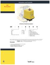
AE Series Numbering System TORQUE 200 400 600 800 1000 Enter all digits of Torque Value OPTIONS 0 – Standard A – One extra switch & cam B – Two extra switches & cams C – Three extra switches and cams D – Heater and Thermostat (15 watt) F – Motor Brake (115 VAC & 24 VAC Only) P - Positioner 4-20 mA T - Transmitter 4-20 mA Note: AE will always be the first two characters of the part number, all digits from torque value must be entered into part number (i.e. 400, 1000 etc.) Only use one digit for voltage depiction (i.e. 1-5). For the options listing you may use more than one character, up to three, (i.e. O, AD or BD etc.) AE-400-3BF : 400 lb. in.; 220 VAC; 2 extra switches and cam, motor brake AE-1000-1D : 1000 lb. in.; 115 VAC; Heater and thermostat 1 Year warranty on positioner & positioner with transmitter 12 VDC not available with positioner Transmitter available with (P) positioner option only Positioner & Tra
Open the catalog to page 1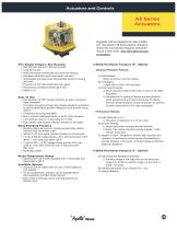
Ruggedly built and designed for easy installation, new Apollo® AE Series electric actuators deliver the most standard features and performance in their class. Now CSA listed all sizes as standard. Five Output Torques, One Housing • 200, 400, 600, 800 and 1,000 inch-pounds • Long Service Life • Newly developed anodized die cast aluminum housing • Fiberglass reinforced nylon cover resists corrosion • Nitrile gasket and seals cover all penetration points in housing and cover • Precision cut and heat treated alloy spur gears • Permanently lubricated enclosed gear train • NEMA 4, 4X Easy To Use •...
Open the catalog to page 2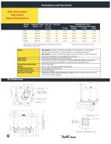
Breakaway Torque Cycle Time Duty Cycle Output (in.-lbs.) 90° Travel Starting or locked rotor current voltage Note: 90' Travel = Travel From Closed position to Open position or vice versa DC current draw is at max. torque 24 VAC current draw at locked rotor 4.6 amp
Open the catalog to page 3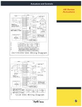
DUE TO HIGH AC INDUCTION FEEDBACK VOLTAGE THROUGH THE CAPACITOR AND TERMINALS 3 & 4. MULTIPLE ACTUATORS CANNOT BE WIRED IN PARALLEL. SEPERATE RELAYS (ISOLATED CONTACTS) MUST BE PROVIDED FOR EACH ACTUATOR. DEVICES CONNECTED TO TERMINALS 3 & 4 MUST BE RATED FOR BENCH TESTING PURPOSES: TO OPEN: JUMP TERMINALS 1 & 3 ONLY CONNECT NEGATIVE (-> TO: TERMINAL 1 CONNECT POSITIVE (+> TO: TERMINAL 5 TO CLOSE: JUMP TERMINALS 3 4 5 ONLY CONNECT NEGATIVE (-) TO TERMINAL 3 CONNECT POSITIVE 1+) TO TERMINAL 1 %ApoHk'' Valves
Open the catalog to page 4All Conbraco Industries catalogs and technical brochures
 Backflow Prevention
76 Pages
 Industrial Products Binder
466 Pages
 Commercial Catalog
292 Pages
 32-100 series
1 Page
 A108
A1082 Pages
 CS & CL SERIES ACTUATORS
3 Pages
 Actuators and Controls
5 Pages
 Industrial Valve
2 Pages
 Gate, Globe & Check Catalog
28 Pages
 Butterfly Valves Catalog
28 Pages
 Backflow Prevention Catalog 2016
76 Pages
 Automatic Control Valves
16 Pages
 APOLLOXPRESS CATALOG
68 Pages
 APOLLOPEX Tools and Valves
4 Pages
 Apollo ® Rack & Pinion
5 Pages
 G series
5 Pages
 LB series
3 Pages
 CS, CL
4 Pages
 PRODUCTS CATALOG
32 Pages
 Top Entry Ball Valve Catalog
44 Pages
 2014/2015 Commercial Catalog
184 Pages
 WATER PRESSURE REDUCING VALVES
20 Pages
 TOP ENTRY BALL VA LV ES
44 Pages
 SAFETY AND RELIEF VALVES
52 Pages
 MIXING VALVES
20 Pages
 Marine Catalog
12 Pages
 Lead Free Products Catalog
71 Pages
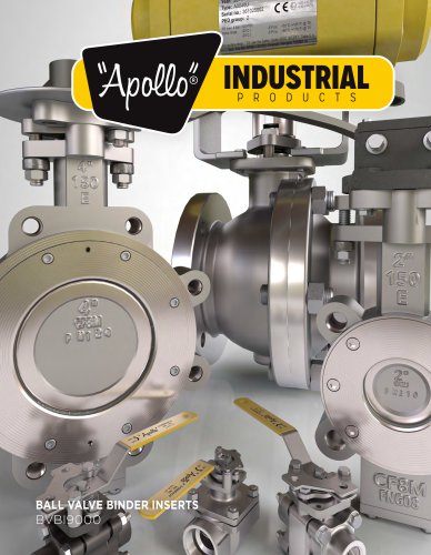
 Industrial Ball Valve Binder Inserts
312 Pages
 Fire Protection Products Catalog
20 Pages
 Check Valve Brochure
20 Pages
 Cast Iron Y-Strainer
12 Pages
 77V series 1/2" - 2"
1 Page
 77V series 2-1/2" - 4"
1 Page
 77W-HC series
1 Page
 LB Series Electric Actuators
3 Pages
 TEE
TEE1 Page
 FEMALE ADAPTER
1 Page
 45 DEGREE ELBOW
1 Page
 MALE ADAPTER
1 Page
 Fitting Dimension Sheet
1 Page
 TS_acutorque_2
6 Pages
 cat_PHBRWGA
16 Pages
 cat_PHBRHYD
40 Pages
 cat_GGC9000
28 Pages
 cat_BFFPCAT
20 Pages
 cat_FSCA9000
12 Pages
 cat_ABBR141G
16 Pages
 cat_AXCAT
76 Pages
 cat_ACVBR9000
16 Pages
 cat_ACCA9000
48 Pages
 cat_CICA9000
28 Pages
 cat_CPCA9000
180 Pages
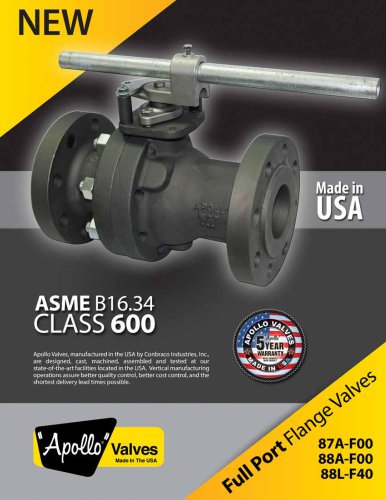
 SERIES 38-500
2 Pages
 THREE-PIECE VALVES
4 Pages
 pipeline strainers
20 Pages
 MARINE VALVES AND FITTINGS
12 Pages
 IN-LINE CHECK VALVES
12 Pages
 CONTROL VALVES
8 Pages
 BACKFLOW PREVENTERS
72 Pages
 BALL VALVES
12 Pages
 ACTUATORS AND CONTROLS
56 Pages


Archived catalogs
 Actuation Catalog
57 Pages
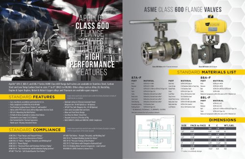 Class 600 Ball Valve_2015
2 Pages
 Class 600 Ball Valve_2014
4 Pages
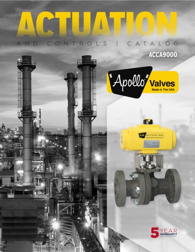 Actuation Catalog ACCA9000
56 Pages
 Conbraco - Catalog
132 Pages
 Conbraco - Strainers CICASTOO
20 Pages


- Fitting
- Rototherm manual valve
- Rototherm control valve
- Rototherm stainless steel valve
- Hydraulic fitting
- Rototherm water valve
- Rototherm ball valve
- Rototherm threaded valve
- Metal fitting
- Rototherm regulating valve
- Liquid filter
- Rototherm flange valve
- Rototherm shut-off valve
- Rototherm flap valve
- Rototherm check valve
- Lever valve
- Nickel-plated brass fitting
- Butterfly valve
- Nut