- Catalogs
- The Comus Group
- Housed & SMD Reed Switches
Housed & SMD Reed Switches
1 /2Pages

Housed & SMD Reed Switches
1 /2Pages
Catalog excerpts
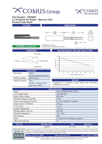
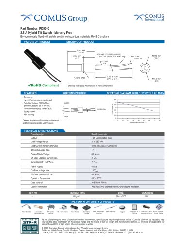
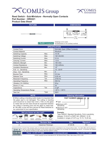
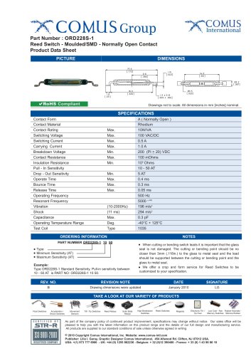
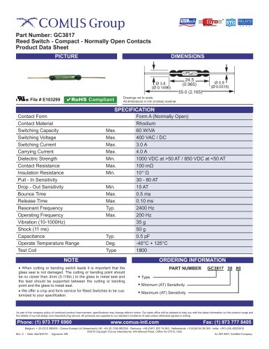
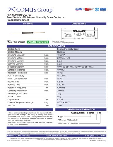
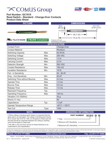
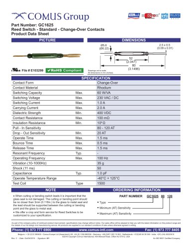
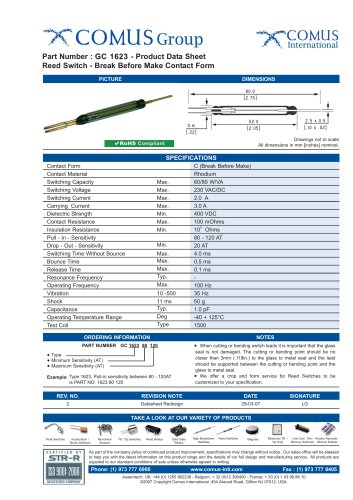
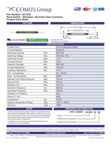
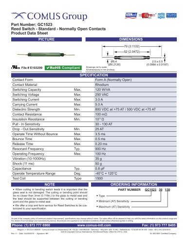
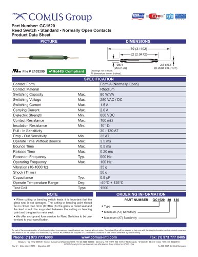
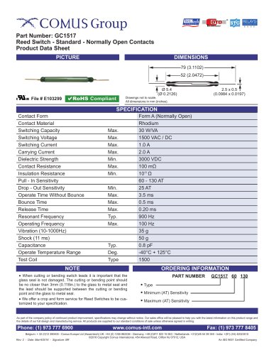
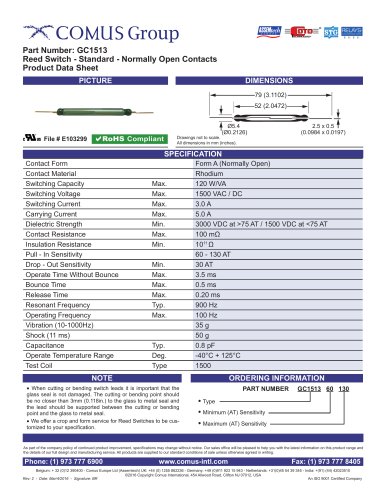
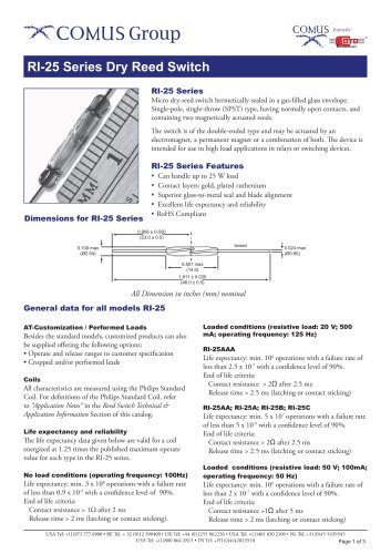
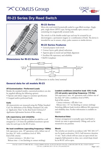
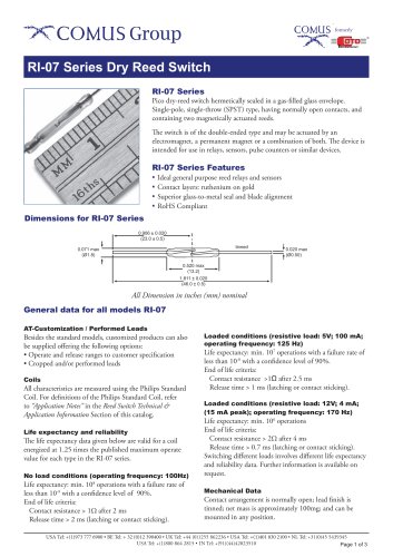
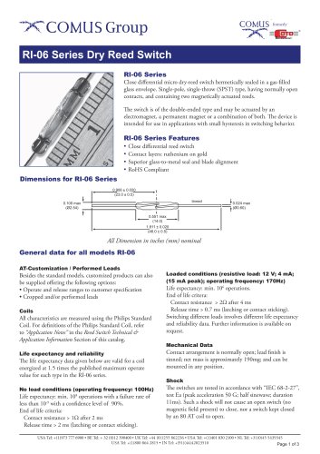
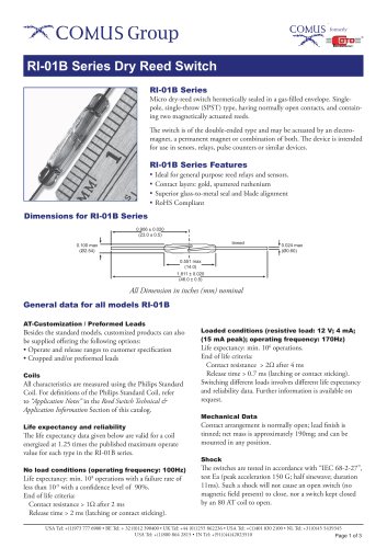
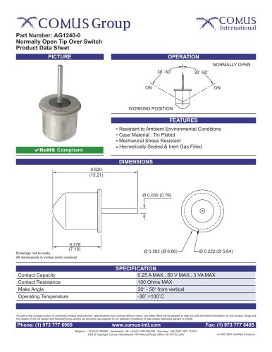
The Comus International group of companies consists of: DESCRIPTION Reed Switches consist of two or three ferromagnetic blades (or reeds) hermetically sealed inside a glass envelope.The construction ensures protection from the external environment. Three types are available: Form A (normally open), Form B (normally closed), and Form C (changeover). Form B reed switches are obtained by two methods: By using normally closed blade of a Form C switch, or, by using a Form A switch, and biasing the contacts closed using a small block magnet.The switch is then able to re-open by the use of another stronger external magnet of opposite polarity. Sensitivity of a reed switch is measured in ampere turns (A.T.) and it should be noted that lower switch (A.T.) ratings are more sensitive as they require less magnetic field strength to operate them.Various voltage and current switching levels are available and contact plating materials can be varied to accommodate specific types of load. Lamp Loads Reed Switches are operated by a magnetic field, via a magnet or a current carrying coil. When the field is removed the switch reverts to its previous state. Operation by a magnet can be achieved in a large variety of ways, either moving the magnet toward and away from the reed either perpendicularly, or parallel to the glass. Reed Switches are used in a variety of Comus Group products including Proximity Switches, Float Switches and Reed Relays. They are now available in housed packages affording protection from damage and Surface Mount styles. With lamp load applications it is important to note that cold lamp filaments have a resistance 10 times smaller than already glowing filaments. This means that when being turned on, the lamp filament experiences a current flow 10 times greater than when already glowing. This high inrush current can be reduced to an acceptable level through the use of a series of current-limiting resistors. Another possibility is the parallel switching of a resistor across the switch. This allows just enough current to flow to the filament to keep it warm, yet not enough to make it glow. Actuation of Reed Switches with a Permanent Magnet (Examples of switching with the use of a moving magnet.) Examples of switching through rotational movement. Direct Actuation: Comus International 454 Allwood Road Clifton New Jersey 07012 U.S.A Tel: (1)973 - 777 - 6900 Fax:(1)973 - 777 - 8405 email: [email protected] Website: http://www.comus-intl.com Comus Europe Limited Unit 7, Rice Bridge Industrial Estate Thorpe - Le - Soken Essex England CO16 0HL Tel: +44 (0)1255 862236 Fax: +44 (0)1255 862014 email: [email protected] Website: http://www.comuseurope.co.uk A magnet moved perpendicularly towards and away from a Reed Switch turns it off and on once. Comus Belgium BVBA Overhaamlaan 40 B-3700 Tongeren Belgium Closed Open A magnet swung towards and away from a Reed Switch operates it once. CONTACT PROTECTION Ring Magnet Lamp load with parallel or current limiting resistor across the switch Cutting and Bending: As the Reed Switch blades are part of the magnetic circuit of a Reed Switch shortening the leads results in increased pull-in and drop-out values. Comus Technology BV Jan Campertstraat 11 6416 SG Heerlen The Netherlands Switching Technologies Gunther B-9, B-10, & C-1 Special Economic Zone (MEPZ) Kadapperi Tambaram Chennai 600 045 India Tel: +31(0)45-54.39.345 Fax: +31(0)45-54.27.216 email: [email protected] Website: http://www.dry-reeds.com Capacitive Loads Unlike inductive loads, capacitive and lamp loads are prone to high inrush currents which can lead to faulty operation and even contact welding. When switching charged capacitors (including cable capacitance) a sudden unloading can occur, the intensity of which is determined by the capacity and length of the connecting leads to the switch. This inrush peak can be reduced by a series of resistors. The value is dependent on the particular application but should be as high as possible to ensure that the inrush current is within the allowable limits. Comus Electronics and Technologies India Private Limited 2nd Floor, 31/33, Anjugam Nagar, 2nd Street, Ashok Nagar, Jaferkhanpet, Chennai 600083 Tamil Nadu, India Tel: +(91)-(44)-42023510 Fax: +(91)-(44)-22628198 email: [email protected] Website: http://www.comusindia.com Closed Magnet With the stationary arrangement of a Reed Switch and magnet, the contact Reeds are closed. Should the magnetic field be diverted away from the Reed Switch by a shield of ferromagnetic material placed between the switch and the magnet, the contacts will open. When the shield is removed, the contact Reeds become magnetically actuated and close. Magnet Closed A ring magnet moved parallel to a Reed Switchs’ axis operates it from one to three times. Inductive Loads Indirect Actuation: Shielding Magnet Tel: +32 (0)12 390400 Fax: +32 (0)12 235754 email: [email protected] Website: http://www.comus.be A magnet moved parallel to a Reed Switch operates it from one to three times. A reverse voltage is generated by stored energy in an inductive load when the reed contacts open. This voltage can reach very high levels and is capable of damaging the contacts. An RC network may be used as shown below to give protection. Closed Magnet Magnetic shield Pull-in Sensitivity: The given pull-in sensitivity of the Reed Switch has a test equipment tolerance of ± 2 AT. For all Reed Switches the standard pull-in sensitivity is given in the table. Other pull-in sensitivities are available on request. Life Expectancy: The life expectancy of a reed switch is dependent upon the load being switched. At maximum rated loads life expectancy is approximately 106 switching cycles. Lower load ratings can increase the life expectancy up to 5x10⁸ operations. The mechanical life expectancy can reach at least 109 operations. Through the switching of inductive, capacitive, and lamps loads, the life expectancy is considerably reduced due to exceeding the specified maximum current. Magnet Biasing Contact Contact Form B or C Normally Closed Contact (Form B) RELAYS -UNLIMITED.com COMPUTER COMPONENTS INC. When cutting or bending Reed Switches, it is important that the glass body should not be damaged. Therefore, the cutting or bending point should be no closer than 3mm (.118) to the glass body. Computer Components Inc. 18-B Kripes Rd. East Granby Connecticut 06026 U.S.A Normally Open Contact (Form C) Tel: (1)401 - 228 - 5459 The above diagram illustrates a resistor/capacitor network for protecting a Reed Switch against high inrush currents. R1 and/or R2 are used depending upon circuit conditions. All dimensions are nominal, in millimeters unless otherwise stated. If further information is required, individual datasheets are available on our websites, and on CD. As part of the group’s policy of continued product improvement, specifications may change without notice. Our sales office will be pleased to help you with the latest information on our products. email: [email protected] Website: http://www.relays-unlimited.com We also have a large network of worldwide agents. These can be seen on any of our websites, or on our company profile brochure. Com/1/Oct14/Iss.4 HOUSED & SMD REED SWITCHES From the Comus Group of Companies All dimensions are nominal, in millimeters unless otherwise stated. If further information is required, individual datasheets are available on our websites, and on CD. As part of the group’s policy of continued product improvement, specifications may change without notice. Our sales office will be pleased to help you with the latest information on our products.
Open the catalog to page 1All The Comus Group catalogs and technical brochures
 PD6016-1
1 Page
 PD5004
1 Page
 PD5003
1 Page
 PDS1000 Series
2 Pages
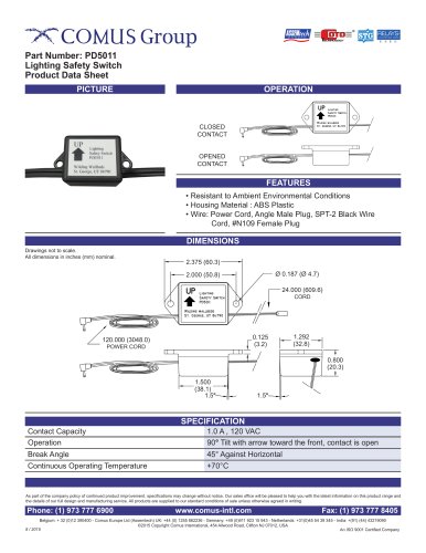 PD5011
1 Page
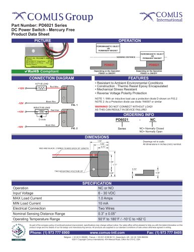 PD6021 Series
1 Page
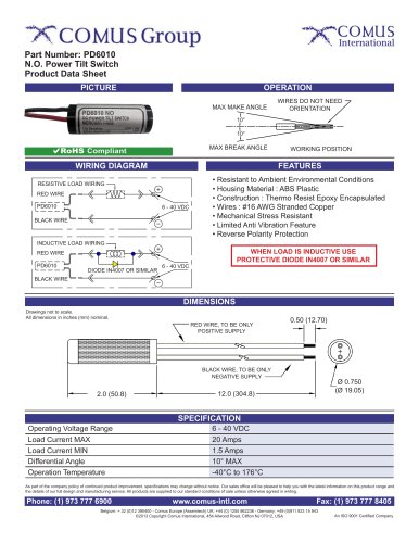 PD6010
1 Page
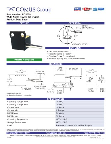 PD5009
1 Page
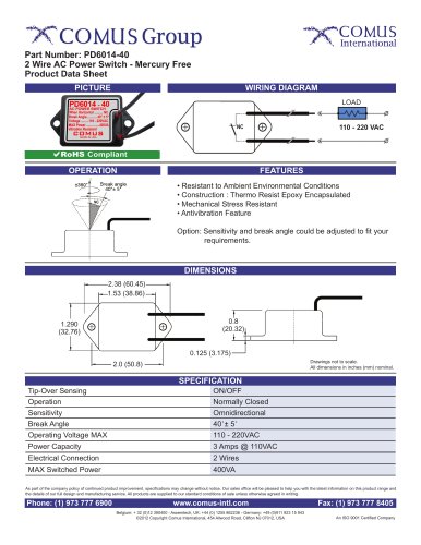 PD6014-40
1 Page
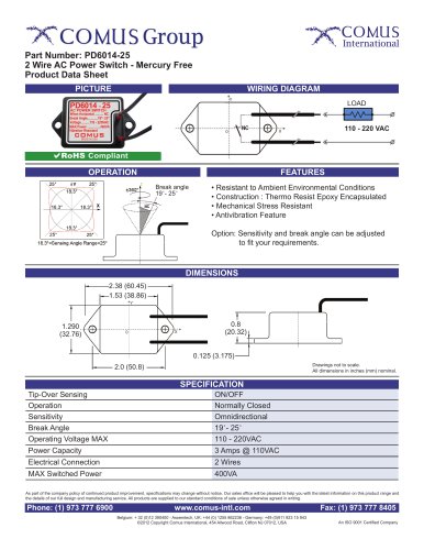 PD6014-25
1 Page
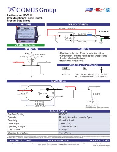 PD6011
1 Page
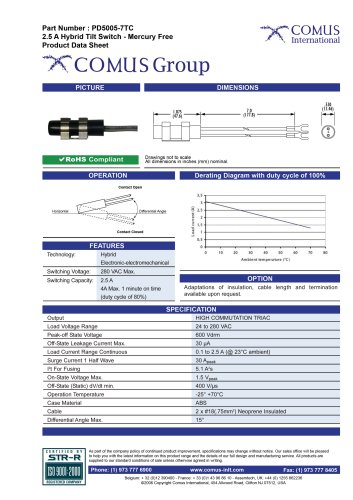 PD5005-7TC
1 Page
 PD5005
1 Page
 PD5000
1 Page
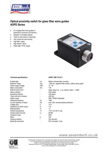 AOPD Series
3 Pages
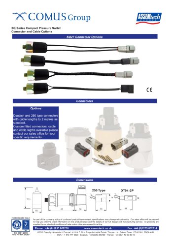
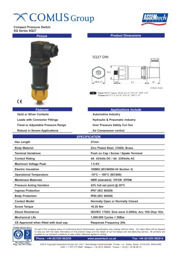 SQ Series SQ27
2 Pages
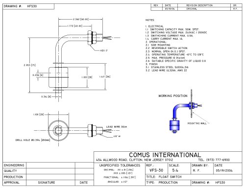 HFS30
HFS301 Page
 SQ Series
1 Page
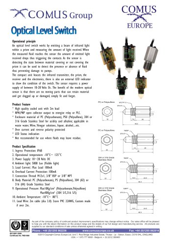 optical level switch
2 Pages
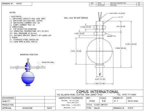 VFS75
VFS751 Page
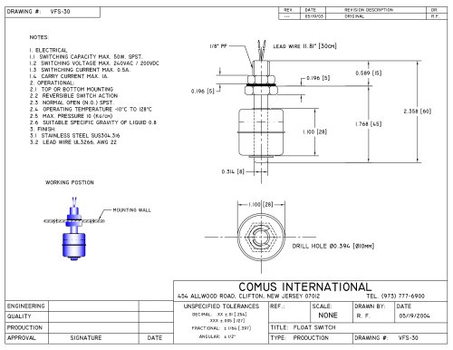 VFS30
VFS301 Page
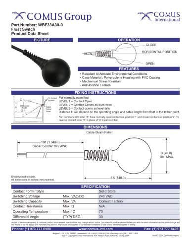 WBF33A30-0
1 Page
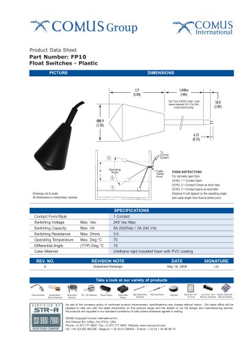 FP10
FP101 Page
 BF32A25-0
1 Page
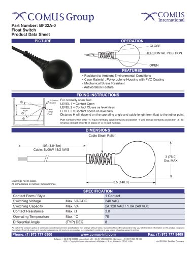 BF32A-0
1 Page
 BF310A-0
1 Page
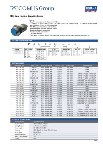 M30
M302 Pages
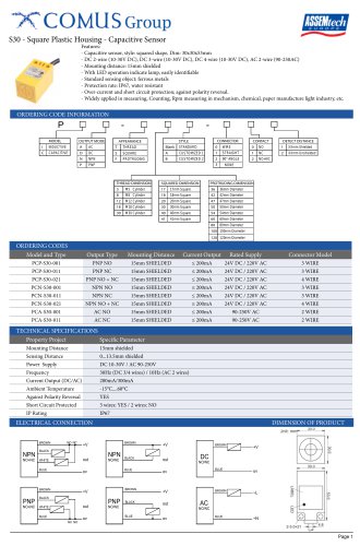 S30
S302 Pages
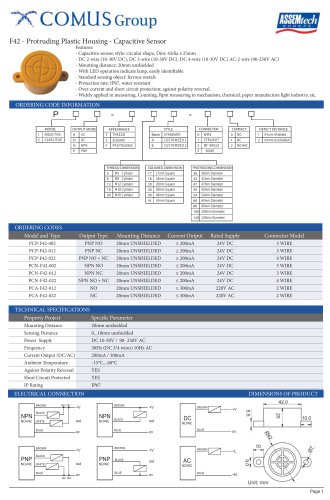 F42
F422 Pages
 F36
F362 Pages
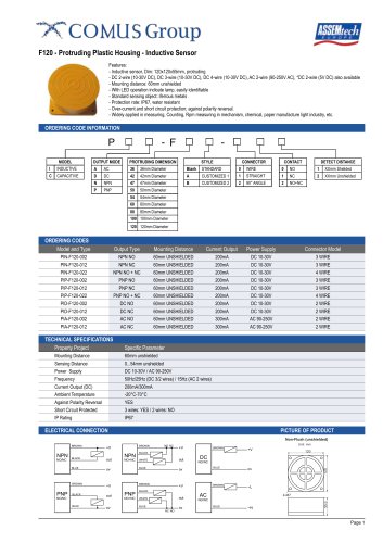 F120
F1202 Pages
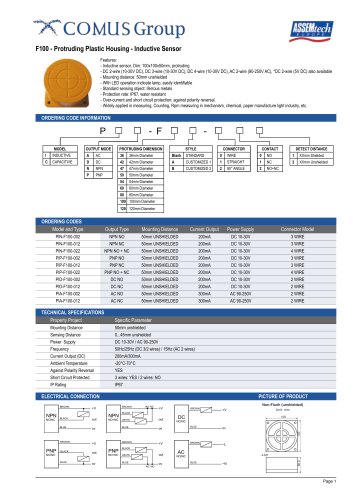 F100
F1002 Pages
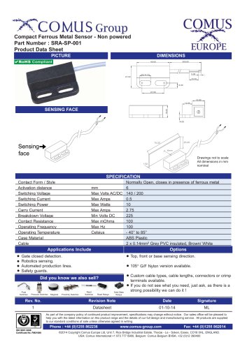 SRA-SP-001
1 Page
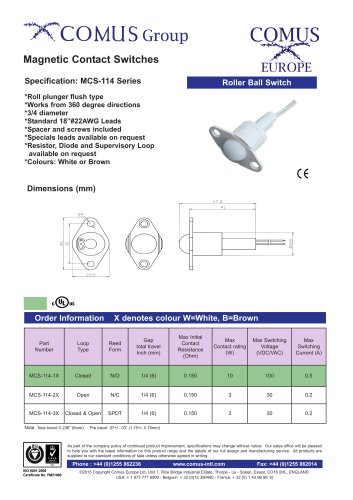 MCS-114 Series
1 Page
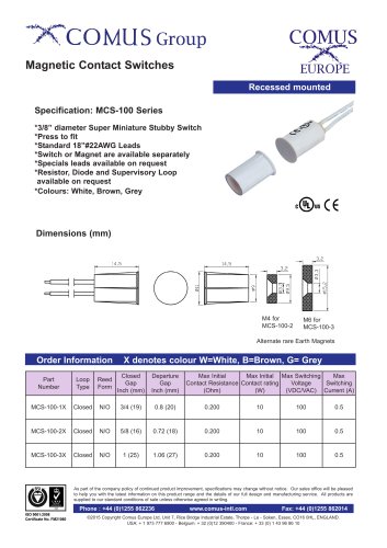 MCS-100
1 Page
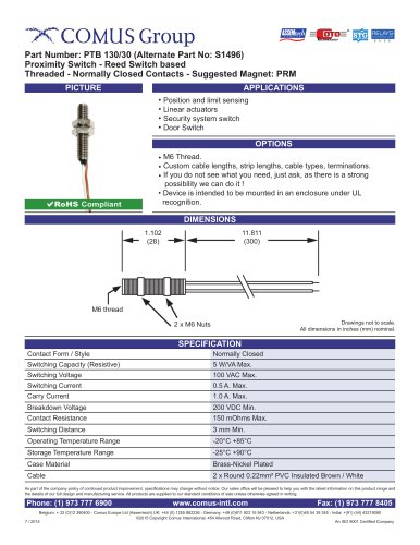 PTB 130/30
1 Page
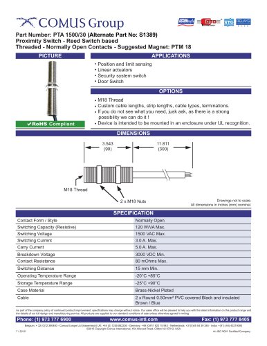 PTA 1500/30
1 Page
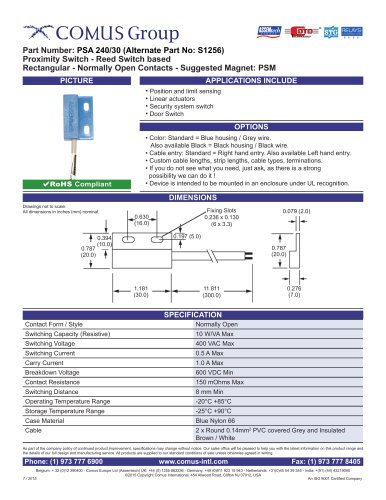 PSA 240/30
1 Page
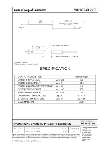 MPS4432SN
1 Page
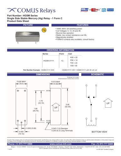 HGSM Series
2 Pages
 HGRM Series
2 Pages
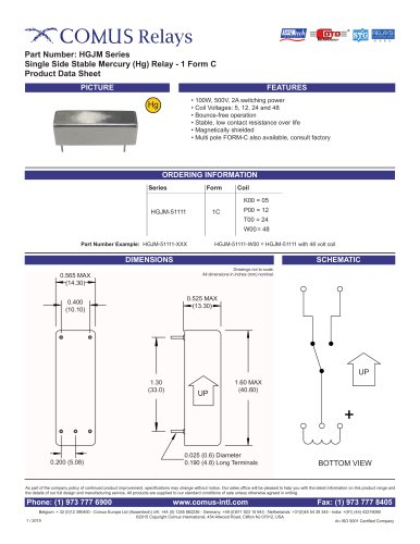 HGJM Series
2 Pages
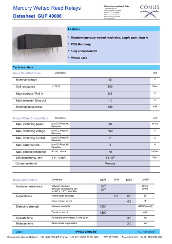 GUP 40008
2 Pages
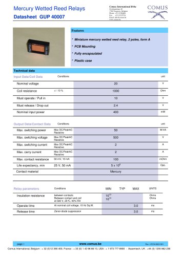 GUP 40007
2 Pages
 GUP 40006
2 Pages
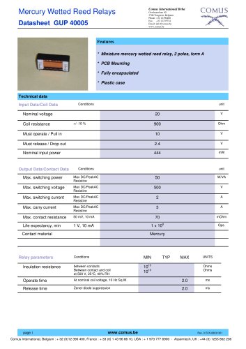 GUP 40005
2 Pages
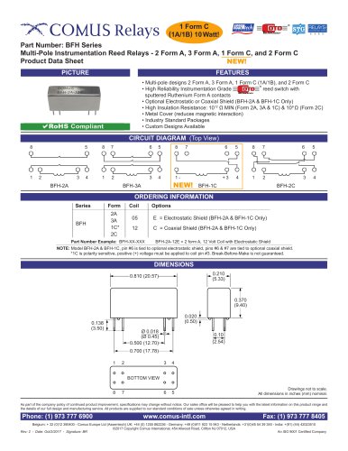 BFH Series
2 Pages
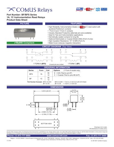 BF/BFS Series
2 Pages
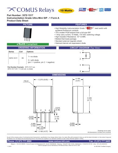 3570.1517
2 Pages
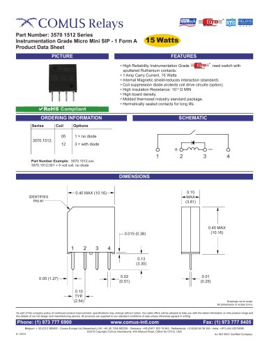 3570.1512 Series
2 Pages
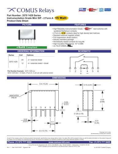 3570.429 Series
2 Pages
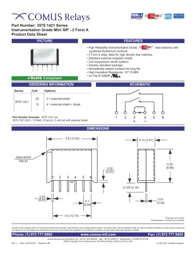 3570.1421 Series
2 Pages
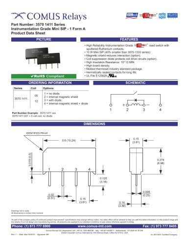 3570.1411 Series
2 Pages
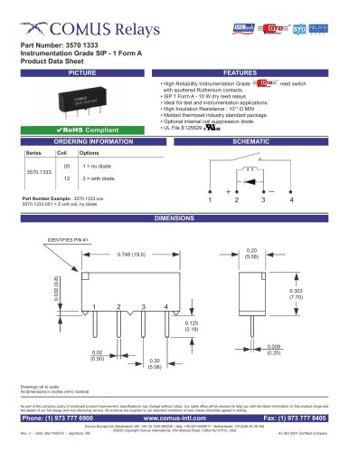 3570/1333
2 Pages
 CGSM Relay PR
1 Page
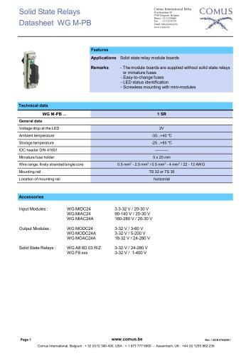 WG M-PB
7 Pages
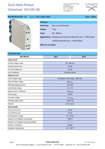 WG M8 6B
3 Pages
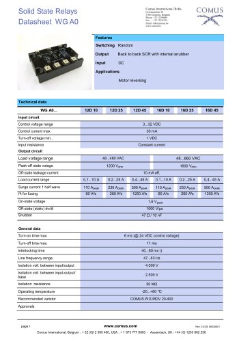 WG A0
WG A05 Pages
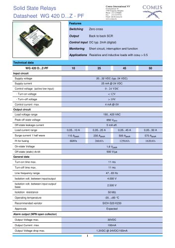 WG 420 T MR
7 Pages
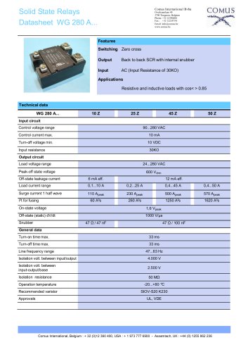 WG 280 A
8 Pages
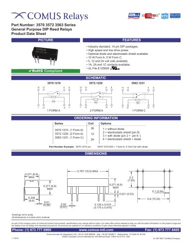 3570/3572/3563 Series
2 Pages
 3570 1419 Series
2 Pages
 3570 1339
2 Pages
 3570 1411 Series
2 Pages
 3570 1331
2 Pages
 HG 108314 Series
1 Page
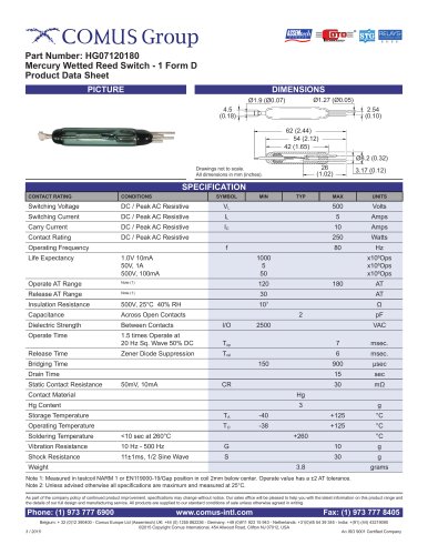 HG07120180
1 Page
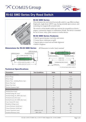 RI-02 SMD Series
4 Pages
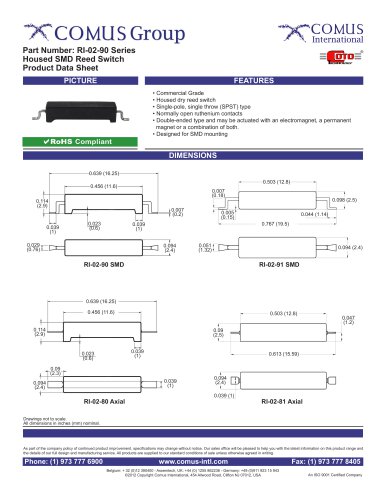 RI-02-90 Series
2 Pages
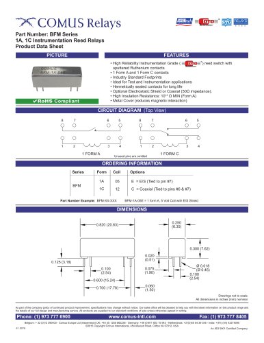 BFM Series
2 Pages
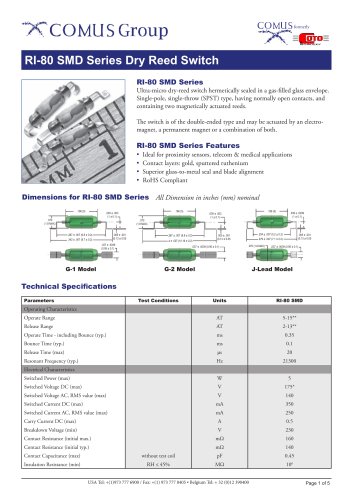 RI-80 SMD Series
5 Pages
 RI-60-90 Series
2 Pages
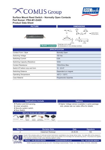 PRA-M1-DA05
1 Page
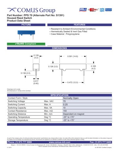 PPS 70
1 Page
 PPS 470
1 Page
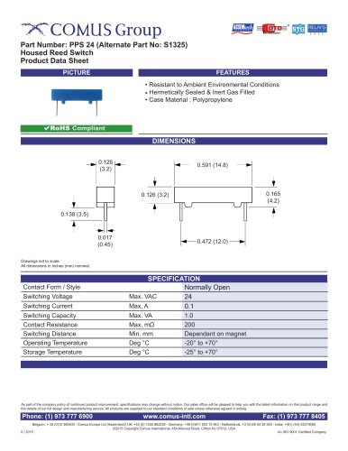 PPS 24
1 Page
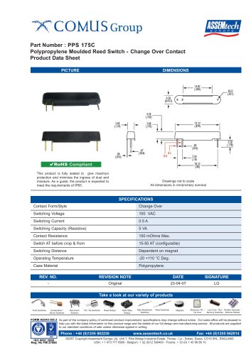 PPS 175C
1 Page
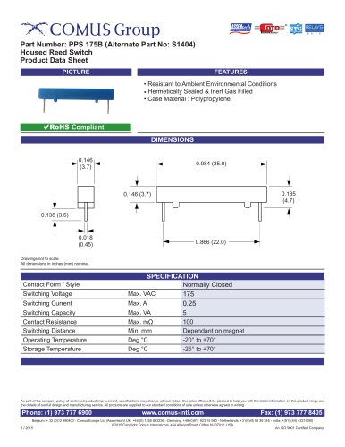 PPS 175B
1 Page
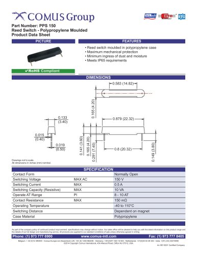 PPS 150
1 Page
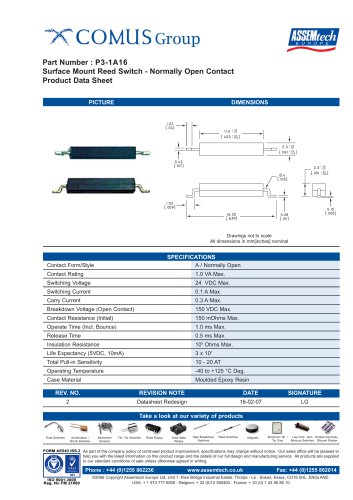 P3-1A16
1 Page
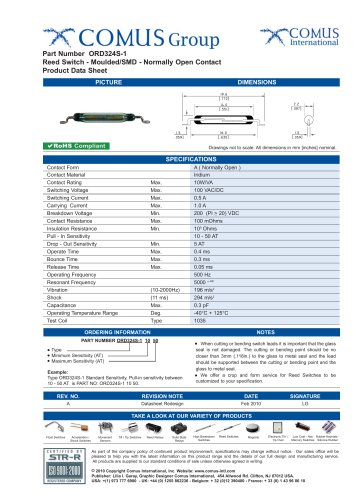 ORD324S-1
1 Page
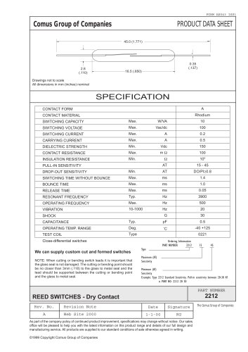 ORD 2212
1 Page
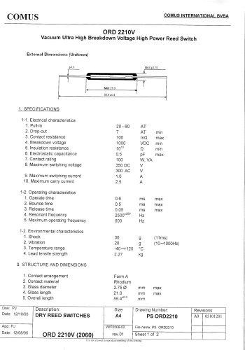 ORD 2210V
2 Pages
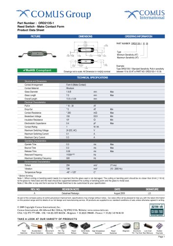 ORD 213S-1
1 Page
 ORD221
1 Page
 ORD228S-1
1 Page
 GC3823
1 Page
 GC3817
1 Page
 GC3723
1 Page
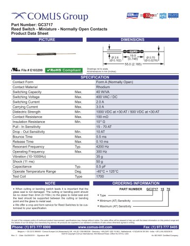 GC3717
1 Page
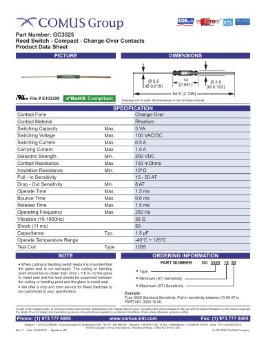 GC3525
1 Page
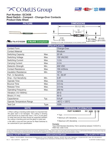 GC3436
1 Page
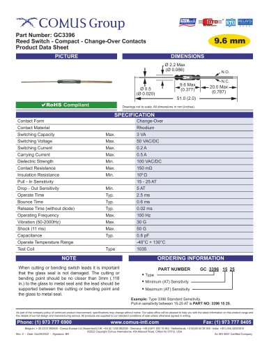 GC3396
1 Page
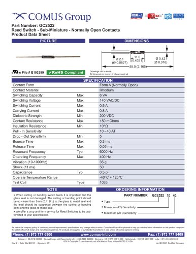 GC2522
1 Page
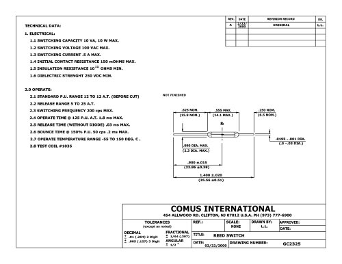 GC 2325
1 Page
 GC2717
1 Page
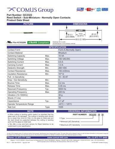 GC2322
1 Page
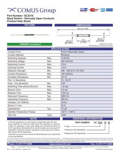 GC2315
1 Page
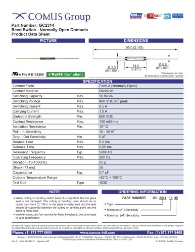 GC2314
1 Page
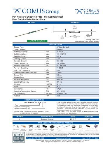 GC2310 (0735)
1 Page
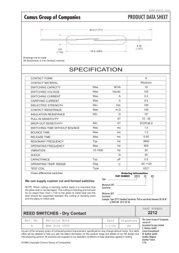 GC 2212
1 Page
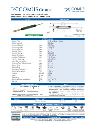 GC 1925
1 Page
 GC1917
1 Page
 GC1915
1 Page
 GC1625
1 Page
 GC 1623
1 Page
 GC1525
1 Page
 GC1523
1 Page
 GC1520
1 Page
 GC1517
1 Page
 GC1513
1 Page
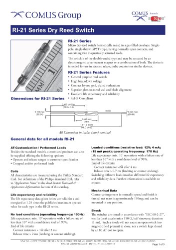 RI-21 Series
3 Pages
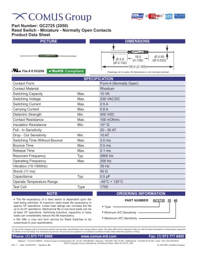 GC2725 (2050)
1 Page
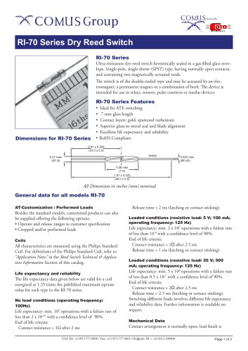 RI-70 Series
3 Pages
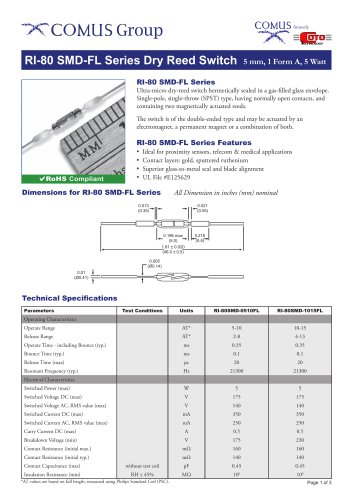 RI-80 SMD-FL Series
3 Pages
 RI-25 Series
3 Pages
 RI-23 Series
3 Pages
 RI-07 Series
3 Pages
 RI-06 Series
3 Pages
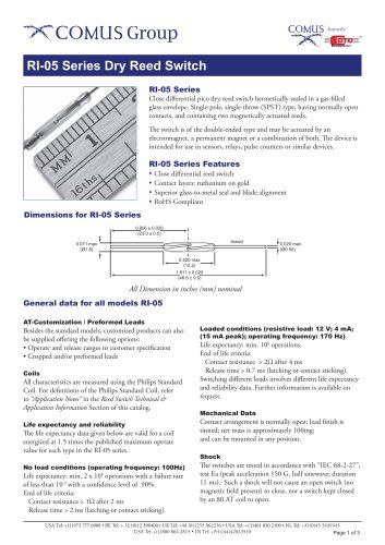 RI-05 Series
3 Pages
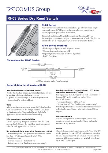 RI-03 Series
3 Pages
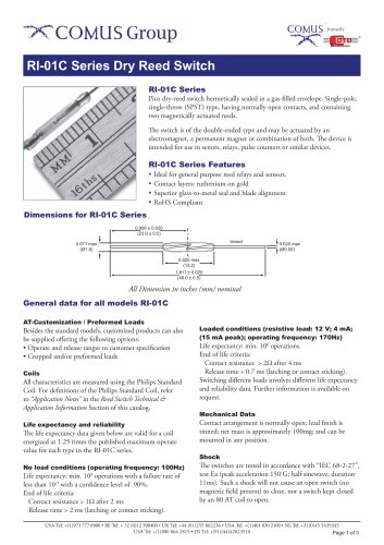 RI-01C Series
3 Pages
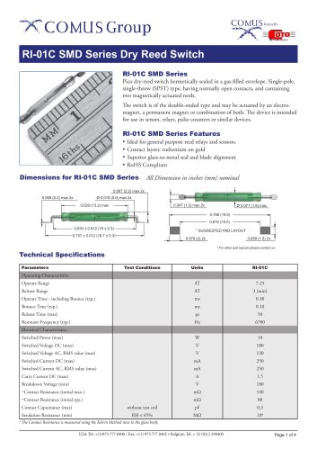 RI-01C SMD Series
4 Pages
 RI-01B Series
3 Pages
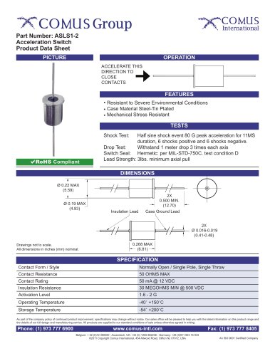 ASLS1-2
1 Page
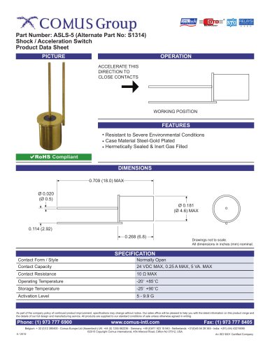 ASLS-5
1 Page
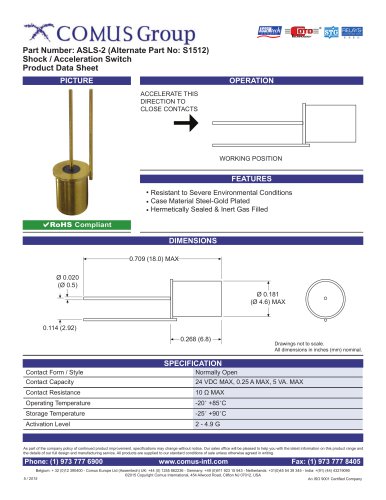 ASLS-2
1 Page
 ASLS-10
1 Page
 ASLS-15
1 Page
 AS1303-0
1 Page
 MS24A/30
1 Page
 MS24
MS241 Page
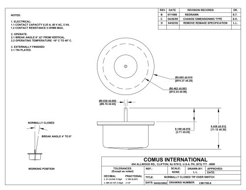
 CM1344-0
1 Page
 MTC175
1 Page
 MTA240
1 Page
 CW1430 Series
1 Page
 CW1317C-0
1 Page
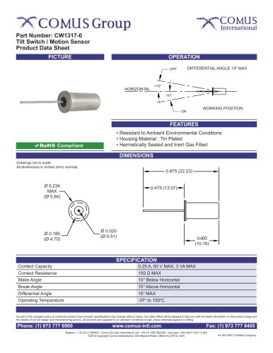 CW1317-0
1 Page
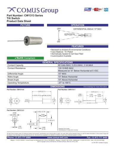 CW1313 Series
1 Page
 CW1307 Series
1 Page
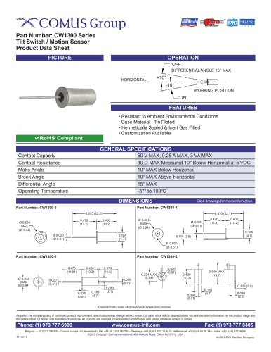 CW1300 Series
3 Pages
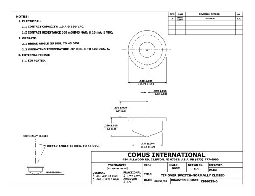 CM6035
1 Page
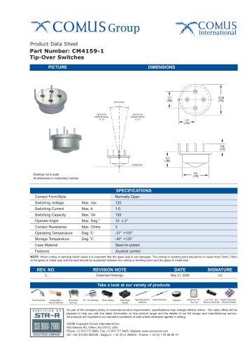 CM4159-1
1 Page
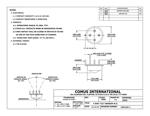 CM4156-1
1 Page
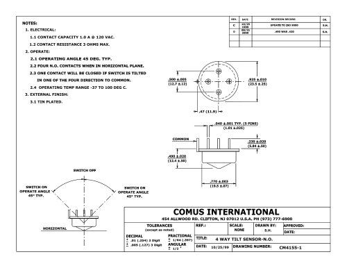 CM4155-1
1 Page
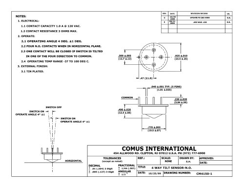 CM4150-1
1 Page
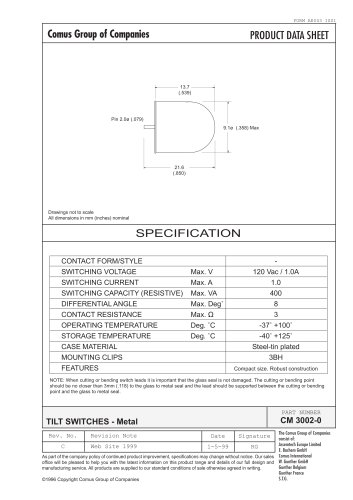
 CM3002
1 Page
 CM3002
1 Page
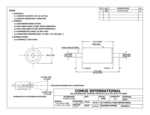 CM2050
1 Page
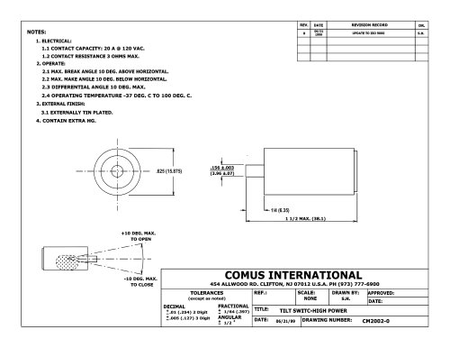 CM2002
1 Page
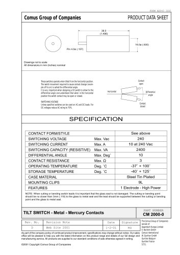 CM2000
1 Page
 CM200
CM2001 Page
 CM1790
1 Page
 CM1745
1 Page
 CM1740-0
1 Page
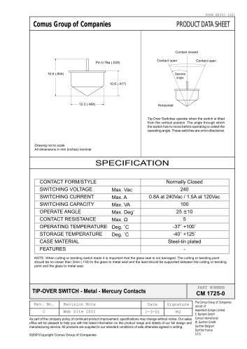 CM1725
1 Page
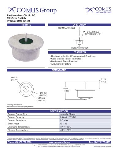 CM1715-0
1 Page
 CM1706
1 Page
 CM1702
1 Page
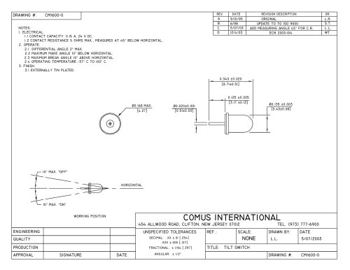 CM1600
1 Page
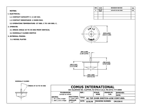 CM1536
1 Page
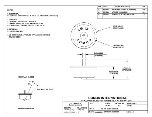 CM1535
1 Page
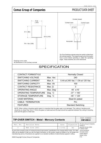 CM1490
1 Page
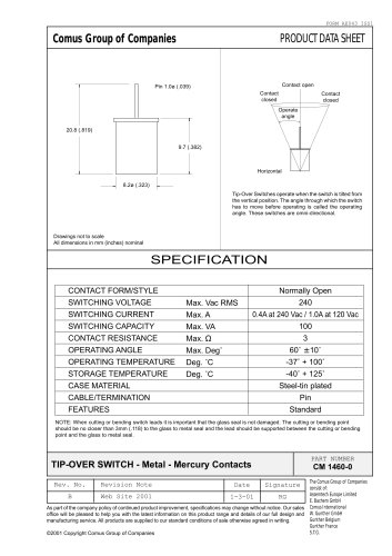 CM1460
1 Page
 CM1445
1 Page
 CM1430 Series
2 Pages
 CM1421-0
1 Page
 CM1370 Series
2 Pages
 CM1360-0
1 Page
 CM1350-1
1 Page
 CM1350-0
1 Page
 CM1323 Series
1 Page
 CM1320-0
1 Page
 CM1300 Series
2 Pages
 CM1230 Series
1 Page
 CM1201 Series
1 Page
 CM1050 Series
2 Pages
 CM1030
1 Page
 CM1020 Series
1 Page
 CM1000 Series
5 Pages
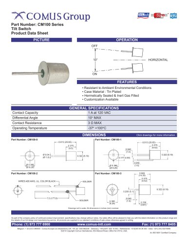 CM100 Series
3 Pages
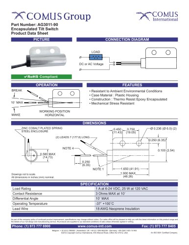 AG3011-90
1 Page
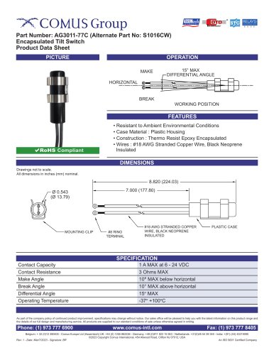 AG3011-77C
1 Page
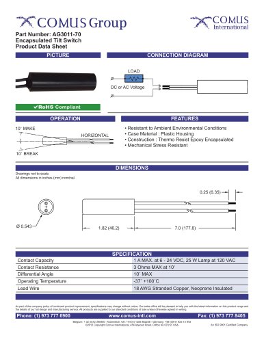 AG3011-70
1 Page
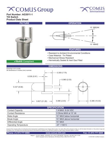 AG3011-1
1 Page
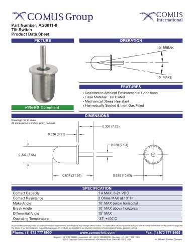 AG3011-0
1 Page
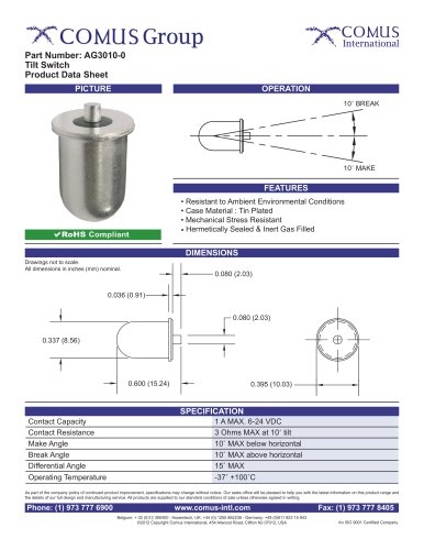 AG3010-0
1 Page
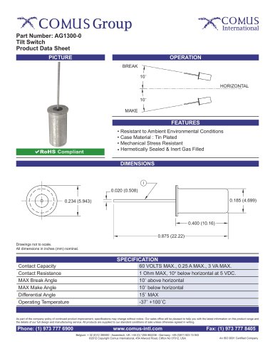 AG1300-0
1 Page
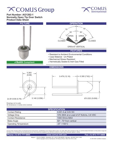 AG1262-1
1 Page
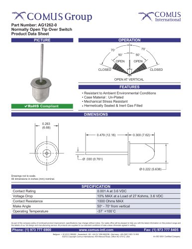 AG1262-0
1 Page
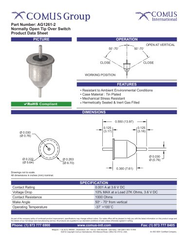 AG1261-2
1 Page
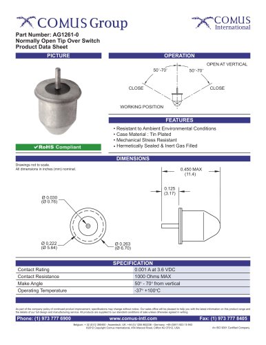 AG1261-0
1 Page
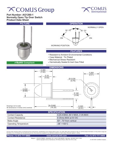 AG1260-1
1 Page
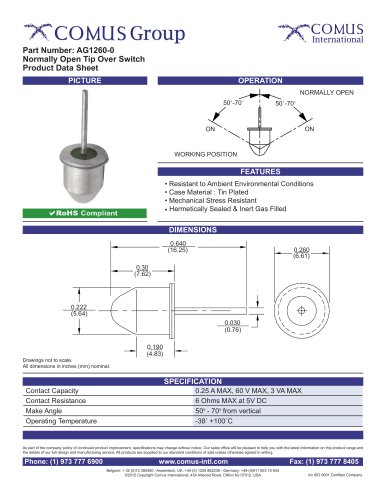 AG1260-0
1 Page
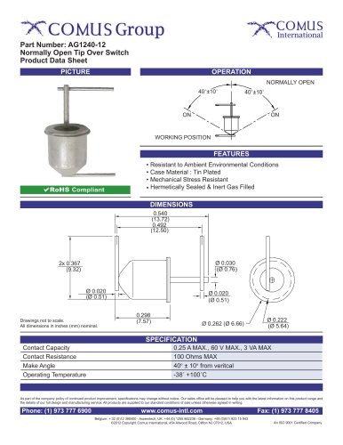 AG1240-12
1 Page
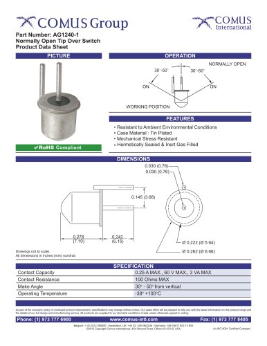 AG1240-1
1 Page
 AG1240-0
1 Page
 SRA-SP series
1 Page
 Reed Switches_2019
10 Pages
 Glass Mercury Switches
2 Pages
 Reed Relays
2 Pages
 High Voltage Reed Relays
2 Pages
 Solid State Relays
2 Pages
 PhotoDMOS Relays
2 Pages
 Float Switches
2 Pages
 Optical Level Switches
2 Pages
 Smart Sensors
8 Pages
 Pressure Switches
2 Pages
 Keypads, Keymats, and Rubber
2 Pages
 Comus Group Line of Products
2 Pages
 Ultrasonic Sensors
2 Pages
 Proximity Switches
2 Pages


Archived catalogs
 Alarm & security switches
12 Pages
 Mercury wetted reed switches
2 Pages
 Non mercury switches
2 Pages
 Glass mercury tilt switches
2 Pages
 Magnets
2 Pages
 Float and level switches
2 Pages
 Mercury tilt switches
2 Pages
 Reed Switches
2 Pages
- Bourn And Koch level switch
- Bourn And Koch single-pole switch
- Bourn And Koch proximity sensor
- Bourn And Koch liquid level switch
- Bourn And Koch accelerometer
- Bourn And Koch switching relay
- Bourn And Koch pressure switch
- Technology switch
- Cylindrical proximity sensor
- Inductive proximity sensor
- Bourn And Koch float level switch
- Bourn And Koch mechanical pressure switch
- Bourn And Koch IP67 proximity sensor
- Bourn And Koch stainless steel level switch
- Bourn And Koch waterproof pressure switch
- Safety electric switch
- Bourn And Koch threaded level switch
- DC proximity sensor
- Bourn And Koch magnetic float level switch
- Bourn And Koch adjustable pressure switch