EM1DC44XBDB
1 /7Pages

EM1DC44XBDB
1 /7Pages
Catalog excerpts
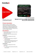
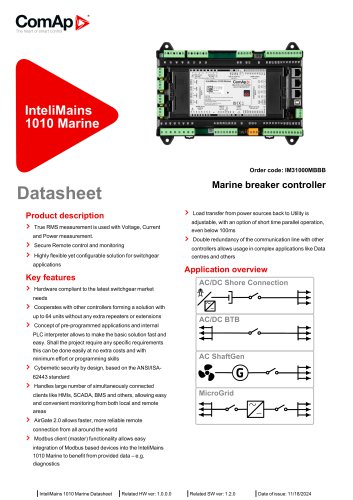
The heart of smart control Inteli DC 4/4 module is an extension module, transducer type, equipped with analog inputs and analog outputs. The module can be used with various types of controllers, purposed for applications where we need to measure precisely direct voltage and direct current (DC Voltage, DC Current) > Unipolar voltage measurement and bipolar current measurement per channel > 2 galvanically isolated input measuring channels Analog Inputs > 4 channels-2 for Voltage and 2 for Current measurement » Voltage measurement input up to 1500 VDC -direct measurement » Current measurement with external shunt up to 3000 ADC (100 mV max voltage input from external shunt resistor) Analog Outputs > 4 channels - 2 for Voltage and 2 for Current measurement » 4 .. 20 mA current loop output (see the transfer function section) | Related SWver: 1.0.0 | Date of issue: 3/25/2024
Open the catalog to page 1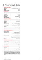
Nominal power supply Acceptable power supply range Nominal power consumption Storage temperature Operating temperature (ambient) Operating humidity Protection degree max. 95 % non-condensing (EN 60068-2-30) IP20, suitable for pollution degree 2 5 .. 25 Hz, ± 1.6 mm 25 .. 100 Hz, a = 4 g max. 500 m/s2 max. 2000 m Number of channels Measurement type Measurement range (sense terminals) Bipolar galvanically isolated ± 100 mV measuring directly via external shunt resistor 4 .. 20 mA measuring via external shunt with external amplifier Max. measurement current depends on the shunt selection (up to...
Open the catalog to page 4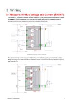
3 Wiring 3.1 Measure: HV Bus Voltage and Current (SHUNT) The module I-DC4/4 allows to measure high bus voltage and current. Wiring for such measurement is shown on Image 4.1. Current is measured via an external shunt resistor. Information of a measured values is provide via current loops. Detailed information can be found in Global Guide. Image 4.1 SHUNT wiring scheme The shunt resistor for current measurement should be connected in the positive pole of a HV bus. On the Image 4.2 configuration is illustrated for current measurement via the external shunt resistor in the negative pole of the HV...
Open the catalog to page 5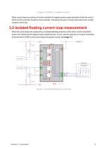
Image 4.2 SHUNT in negative branch When current loops are read by a ComAp controller the negative power supply terminals of both the modul IDC4/4 and the controller should be interconnected. This allows the return current to flow back to the module (closed current loop). 3.2 Isolated floating current loop measurement When the current loops are measured by an isolated (floating) external unit the return current cannot flow back to the module via the negative power supply terminal. In such case the external unit must be connected to the terminal 4 (COM) so the current loops are properly closed,...
Open the catalog to page 6
Revision number Related sw. version 3 1.0.0 Note Author Product sticker The heart of smart control E-mail: [email protected] Web: www.comap-control.com ©ComAp. Features and specification are subject to change without prior notice.
Open the catalog to page 7All ComAp catalogs and technical brochures
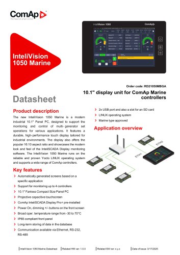 RD21050MBGA
4 Pages
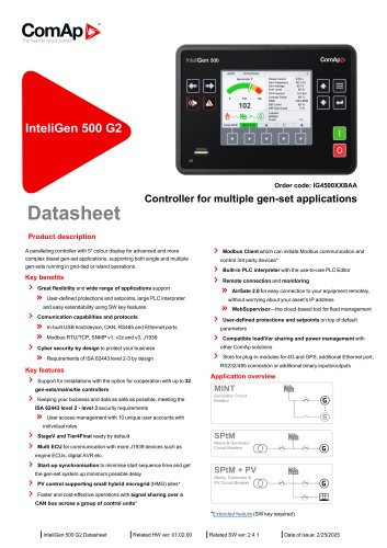 IG4500XXBAA
5 Pages
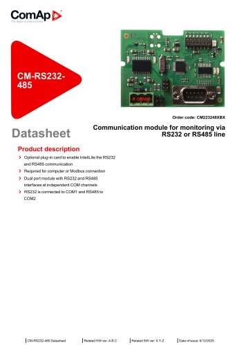 CM223248XBX
3 Pages
 IG4500XXBAA
5 Pages
 IL3LAMF9BAA
4 Pages
 ID2IPUXXBAA
4 Pages
 BC212V05BOB
4 Pages
 RD2IV18TBPE
4 Pages
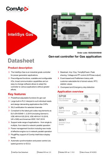 IS2GASXXBAB
4 Pages
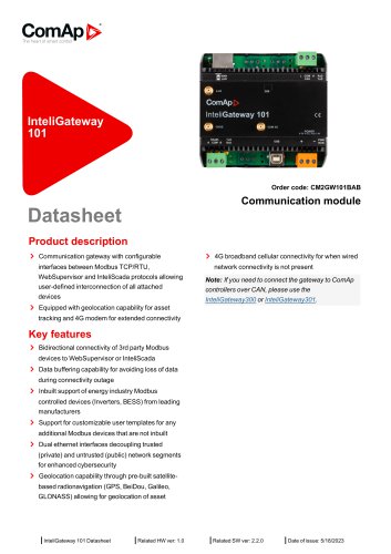 CM2GW101BAB
4 Pages
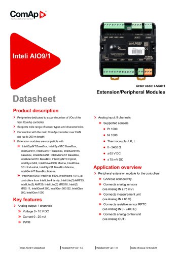
 I-AIO9/1
4 Pages
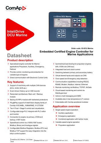
 ID-DCU Marine
2 Pages
 OT1A3GGPACX
5 Pages
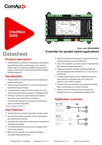
 INEO6000BBB
6 Pages
 INEO6000BBB
5 Pages
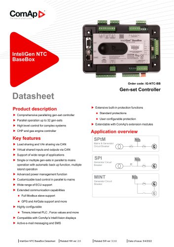 IG-NTC-BB
4 Pages
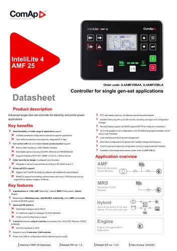 IL4AMF25BAA, IL4AMF25BLA
4 Pages
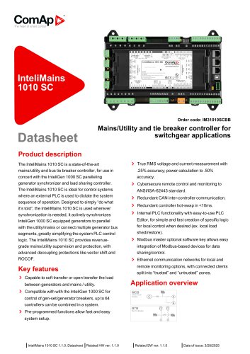 IM31010SCBB
5 Pages
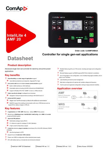 IL4AMF20BAA
4 Pages
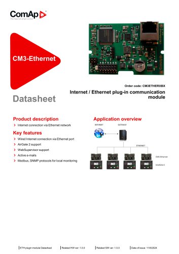 CM3ETHERXBX
2 Pages
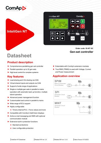 Gen-set controller
4 Pages
 Marine breaker controller
5 Pages


- Display module
- LCD display panel
- Automation software solution
- Industrial display panel
- Cloud-based software
- Color display panel
- Monitoring software solution
- Communication gateway
- Protection relay
- Fieldbus gateway
- Motor controller
- Industrial communication router
- Serial gateway
- Ethernet communication router
- Wireless gateway
- Cellular communication router
- RS-232 display panel
- DC motor controller
- RS-485 gateway
- Communication module