Catalog excerpts

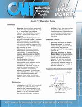
Air Filter: Check and clean/change as required. The frequency of cleaning/changing is dependent on environment and plant air system. Do not allow excess water to fill filter bowl. Installation Mounting: Mounting holes are located in the front and rear end caps. The use of ݔ socket head cap screws is required. The Slide-A-Mark markers require a sturdy, level platform for mounting. Air Requirements: Compressed air is required on all Slide-A-Markٙ markers CMT recommends a ݔ shop airline. Maximum operating pressure of 100 psi, minimum operating pressure of 25 psi. The marker has 3/8 NPT advance and retracting air ports. Adjustments: Increased pressure marks deeper. Decreased pressure marks lighter. To regulate marking pressure, adjust regulator on the FRL (Filter/Regulator/Lubricator unit). Sold separately. Maintenance Rod Orientation: All air and (electrical) power should be disconnected before adjusting the rod orientation, as well as any maintenance. The model 751 rod is keyed to maintain orientation. This radial orientation can be easily adjusted by loosening the front collar clamp (751-29) screw. Then rotate the rod to the desired orientation and retighten clamp collar. Do not over- tighten or the actuated marker will not fire. Pneumatic Controls Electrical Sequence for Spring Return Valve: Electrical Sequence for Double Solenoid Valves: To advance marker, energize solenoid ԓA. To return marker and reset, de-energize solenoid ԓA after part is marked. To advance marker, energize solenoid ԓA. To return marker and reset, de- energize solenoid "AԔ and energize solenoid BӔ. Note: The 751-E1 retract sensor indicates fully retracted position of the marker and may be used to de-energize solenoid BӔ. Suggested Pneumatic Control Diagram > Marker Sol AӔ Standard 4-Way Valve 1/2 Shop Air FRL Combo Unit Sol ԓB 1/2Ԕ Tube RӔ 1/2 Tube Lubrication: Add 10W "light" industrial hydraulic oil to lubricator bowl and adjust oil flow to approximately 1 drop for every 30-50 cycles. The Model 751-XX-XX-XX-NL is a non-lube system and does not require any lubrication. >
Open the catalog to page 1
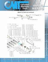
Model 751 Parts List >
Open the catalog to page 2
Model 751 Parts List continued >
Open the catalog to page 3
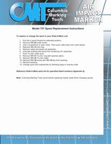
To replace or change the spool in your Slide-A-Mark unit: 751-24 collar screw. 3. Use a screwdriver to open collar. Then push collar back over outer sleeve. 4. Remove 1. Pull rod or spool forward to extended position. 2. Remove 751-13 751-13 lock ring. 5. Remove collar and guide rod assembly. 6. Unscrew bushing and spool from remaining 751 assembly. 7. Push Tru-Arc collar back. 8. Remove Tru-Arc ring with spanner pliers. 9. Remove 751-32 Tru-Arc collar. 10. Remove 751-18 screw and 751-19 key from bushing. 11. Remove bushing. 12. Change spool and reassemble by following steps in reverse...
Open the catalog to page 4All Columbia Marking Tools catalogs and technical brochures
-
Roll Marking Methods & Machines
24 Pages
-
Hot Stamp Catalog
12 Pages
-
Automatic Air Impact Markers
24 Pages
-
Hand Tools
20 Pages
Archived catalogs
-
Stamps Catalog
8 Pages
-
Fiber Laser Marker
2 Pages
-
PR751 Slide-a-Mark Machine
2 Pages
-
Handy Andy
2 Pages
-
Hand Held DMM20
1 Pages
-
Lunch and Learn
2 Pages
-
Hot Stamp Presses
2 Pages
-
Square Dot
2 Pages
-
Easy Marker
2 Pages
-
CMT UID Contract Marking
1 Pages
-
M10/E10 Embosser
2 Pages
-
Concrete Stamps
1 Pages
-
DPS Dot Peen Scribe System
2 Pages
-
PM Micro A Dot Peen
2 Pages
-
Hand Held HMG60
1 Pages
-
In Line Marker
1 Pages


