Catalog excerpts

GLOBOIDAL CAM SERVO TABLES RIGS04 - RIGS06 - RIGS09 Flexible programming High precision Rigid output turret mounted on crossed roller bearings High dynamic performance Planetary gearbox pre-arrangement for customer preferred motor available Compact sealed aluminium housing Universal mounting positions Long life lubrication http://www.cofil.com - E-mail: cofil@cofil.com Via G. Rossini 26 - 24040 Casirate D’Adda Bg IT Phone +39 0363 3251
Open the catalog to page 1
7 Optional reference holes 9 Optional reference holes General section RIGS04 Technical characteristics RIGS06 Technical characteristics Technical characteristics 10 Selection 11 Overall dimensions 11 Optional reference holes RIGS04 - RIGS06 - RIGS09 ► ► ► General section 12 Load capacity of the output bearing13 Lubrication - Table mounting positions - Reducer input side 14 Ordering codes
Open the catalog to page 3
The units of measure comply with the SI international metric index General manufacturing tolerances comply with standard UNI – ISO 2768-1 UNI EN 22768-1 Illustrations and drawings according to 3970 (ISO 128-82) The drawings are represented with the traditional method Colombo Filippetti SpA reserves itself the right to make changes, at any time, for the purpose of improving its products. Therefore, the data contained in this catalogue are not binding. This catalogue supersedes all earlier versions. It is prohibited to reproduce, even in partial form, the content and the illustrations...
Open the catalog to page 4
RIGS04 RIGS06 RIGS09GLOBOIDAL CAM SERVO TABLE General RIGS tables are globoidal constant speed cam units equipped with a planetary gearbox. The globoidal cam turns an output disc carrying a set of roller followers. Globoidal cam and output disc are preloaded one against the other to guarantee zero backlash in any position of the output disc. The preload system, the zero backlash and the needle rollers ensure smooth motion, high rigidity and repeatability, high efficiency and a unit long life. RIG Servo units (RIGS) are available in 3 sizes: RIGS04, RIGS06 and RIGS09. STANDARD CONFIGURATION...
Open the catalog to page 5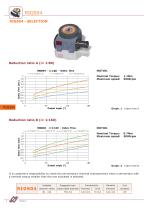
Reduction ratio A (i= 1:80) MOTOR. Nominal Torque: Maximum speed: Reduction ratio B (i= 1:160) MOTOR. Nominal Torque: Maximum speed: It is customer’s responsibility to check the servomotors’ thermal characteristics when a servomotor with a nominal torque smaller than the one indicated is selected. reduction ratios output plate diameter
Open the catalog to page 6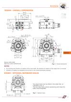
RIGS04 NOTES • By reversing the direction of rotation of the input shaft, the direction of rotation of the output disc is reversed. • Direction of rotation as indicated by the arrows in the overall dimensions drawing. RIGS04 - OPTIONAL REFERENCE HOLES Two dowel holes can be drilled in the table feet, as indicated in Fig. 4. The two holes allow precise positioning and make the table interchangeable.
Open the catalog to page 7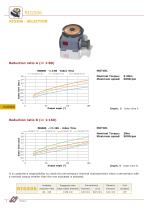
Reduction ratio A (i= 1:80) MOTOR. Nominal Torque: Maximum speed: Reduction ratio B (i= 1:160) MOTOR. Nominal Torque: Maximum speed: It is customer’s responsibility to check the servomotors’ thermal characteristics when a servomotor with a nominal torque smaller than the one indicated is selected. reduction ratio output plate diameter
Open the catalog to page 8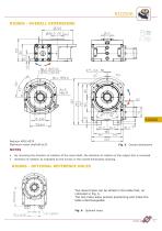
Reducer APEX AE70 Maximum motor shaft Overall dimensions By reversing the direction of rotation of the input shaft, the direction of rotation of the output disc is reversed. Direction of rotation as indicated by the arrows in the overall dimensions drawing. RIGS06 - OPTIONAL REFERENCE HOLES Two dowel holes can be drilled in the table feet, as indicated in Fig. 6. The two holes allow precise positioning and make the table interchangeable. Optional holes
Open the catalog to page 9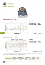
Reduction ratio A (i= 1:80) MOTOR. Nominal Torque: Maximum speed: Reduction ratio B (i= 1:160) MOTOR. Nominal Torque: Maximum speed: It is customer’s responsibility to check the servomotors’ thermal characteristics when a servomotor with a nominal torque smaller than the one indicated is selected. reduction ratios output plate diameter
Open the catalog to page 10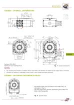
Maximum motor shaft 024x38 NOTES • By reversing the direction of rotation of the input shaft, the direction of rotation of the output disc is reversed. • Direction of rotation as indicated by the arrows in the overall dimensions drawing. Two dowel holes can be drilled in the table feet, as indicated in Fig. 8. The two holes allow precise positioning and make the table interchangeable.
Open the catalog to page 11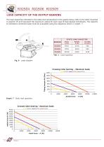
RIGS04 RIGS06 RIGS09LOAD CAPACITY OF THE OUTPUT BEARINGThe load capacities indicated in the table and represented in the graphs below refer to the table mounted in position V5 and represent the maximum values for each type of load applied individually. The capacity to withstand combined loads must be evaluated using the diagrams shown in Graph. 7. Axiale force -A [N] Graph. 7 Static load capacities
Open the catalog to page 12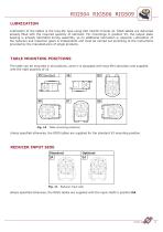
RIGS04 RIGS06 RIGS09 LUBRICATION Lubrication of the tables is the long-life type using ISO VG150 mineral oil. RIGS tables are delivered already filled with the required quantity of lubricant. For mountings in position V5, the output plate bearing is already lubricated during assembly, so no additional lubrication is required. Lubrication of the reducers and reduction gears is independent and must be carried out according to the instructions provided by the manufacturers of single products. TABLE MOUNTING POSITIONS The table can be mounted in all positions, since it is equipped with long-life...
Open the catalog to page 13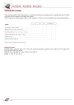
RIGS04 RIGS06 RIGS09 ORDERING CODES The ordering code of the RIGS tables is created by following an alphanumeric classification and formed according to the diagram provided here below. When placing an order, please refer to this diagram in order to avoid mistakes and misunderstandings Size (RIGS04 - RIGS06 - RIGS09) Reduction ratio (i=1:80), B (i=1:160) Mounting position (V5, V6, ..., B8 - Pag. 13 - Fig. 10) Gearbox input side (DA, SA, - Pag. 13 - Fig. 11) Output hub (VCT) Optional reference holes (F) Describe clearly any additional features required. Ordering code: RIGS06 table, reduction...
Open the catalog to page 14
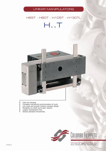
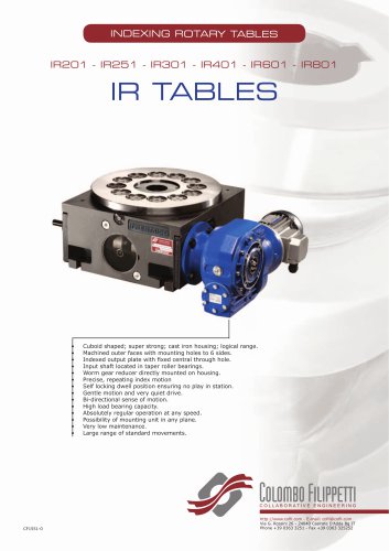
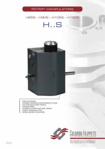
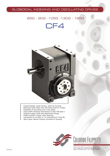
Compact double spherical cam mechanism for mechanical automation Combination of flat cam and globoidal profiled cam Globoidal cam mechanism with four synchronized intermittent movements. Bilateral outputs. Mechanism with different cams Parallel shaft mechanism with flat cam producing seven synchronized intermittent and oscillating ColomFilippetti Flat cam with conjugate profiles
Open the catalog to page 16All COLOMBO FILIPPETTI catalogs and technical brochures
-
SRP
28 Pages
-
RIGIDIAL EN
40 Pages
-
Product Catalogue
19 Pages
-
SERVO ROLLER POSITIONER
12 Pages
-
CF3
16 Pages
-
H..S
28 Pages
-
RIGP
24 Pages
-
IR1601 - IR1801 - IR2001
20 Pages
-
IR1001 - IR1301
20 Pages
-
RIG04 - RIG06 - RIG09
32 Pages
-
INTERMITTENT MECHANISM
20 Pages
-
Parallel oscillating drives
16 Pages
-
Output overload clutches
6 Pages
Archived catalogs
-
FRET SAW MACHINES "HOBBY 50"
2 Pages


