
- Catalogs
- COLOMBO FILIPPETTI
- RIGIDIAL EN


RIGIDIAL EN

RIGIDIAL EN
- Cycle on Demand: Suitable for applications with extended dwell periods, controlled by a cam and sensor system that signals the PLC to halt the motor during the mechanical dwell period.
- Continuous Rotation: Ideal for high-speed applications where the machine cycle completes in one revolution of the input shaft, synchronized with the main shaft rotation.
- Standard configuration with reduction gear and self-braking motor (VLRA).
- Configuration with short input shaft (VS).
- Optional output plate configurations with various hub and hole specifications.
- Optional configurations for ceiling or inverted mounting with reference holes for precise assembly.
- Load capacity and lubrication details.
- Mounting positions and preparation for worm reduction gears.
- Use of torque limiters and E-Cam control systems.
- Precision and concentricity measurements for various configurations.
Catalog excerpts

Smart Automation Globoidal Cam Indexing Tables TECHNICAL CATALOGUE
Open the catalog to page 1
Content index General - Operation Table sizing - Sample applications Configurations and variants chart Configuration with reduction gear and self-braking motor (VLRA) Configuration with short input shaft (VS) Optional configurations of the output plate Configuration with reduction gear and self-braking motor (VLRA) Configuration with short input shaft (VS) Optional configurations of the output plate Optional configuration for ceiling or upside down mounting - Optional reference holes Configuration with reduction gear and self-braking motor (VLRA) Configuration with short input shaft (VS) Optional...
Open the catalog to page 2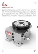
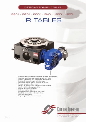
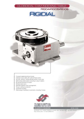
RIGIDIAL Globoidal cam indexing tables RIGIDIAL tables are globoidal cam indexing tables that transform continuous rotary motion into indexing motion. The indexing plate rests on a large-diameter crossed roller bearing that can withstand high axial and tilting loads while maintaining excellent levels of accuracy and rigidity. The cam assures high wear resistance, smooth running, accurate and repeatable positioning without any backlash at the station. A wide range of standard movements is available, including the 2-station movement (180° rotation), which is ideal for tilting or piece exchange...
Open the catalog to page 3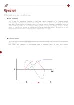
Operation RIGIDIAL tables can be used in two different ways: Cycle on demand This is used for applications featuring a long dwell period compared to the indexing period. In this operating mode, the dwell period is determined by means of a cam which, mounted directly on the table input shaft, operates a sensor that signals to the PLC to stop the motor or disengage a clutch-brake unit in the mechanical dwell period of the cam. At the end of the assembly, production and checking operations, the PLC restarts the motor in order to rotate the output plate up to the next station, then waits for the...
Open the catalog to page 4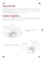
Sizing of the table The rotary table is sized starting from a calculation of the torque required at the output. This torque has to take into account the inertia of the customer’s application, the moment of friction, and the torques due to external, static or dynamic forces requested at the output. For the purpose of avoiding vibrations during rotation, it is important to evaluate the ratio of the equivalent ratio of inertia to the pitch radius of the table cam followers. It is also important to use the proper service factor when sizing the reduction gear. Examples of applications The use of this...
Open the catalog to page 5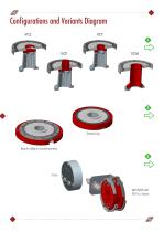
Configurations and Variants Diagram VCS Standard ring Ring for ceiling or inverted mounting
Open the catalog to page 6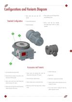
Configurations and Variants Diagram Table centre with cover seal (VCS version) Standard Configuration Crossed roller bearing ring Universal mounting Worm reduction gear with torque limiter and self-braking motor MID or CM4 type cam assembly with double phase switch for consent operation Accessories and Variants Cam with hardened and ground profile Reversed direction pertaining to the rotation of the motion input shaft-output plate Output version normal fixed central through hole without fixing holes (VCT version) Output version with large fixed central through hole without fixing holes (VCM version)...
Open the catalog to page 7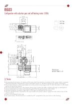
Configuration with reduction gear and self-braking motor (VLRA) 10.7 kg 23.6 lbs Notes • By reversing the direction of rotation of the input shaft, the direction of rotation of the output shaft is reversed, while the kinematic characteristics of the intermittent motion in standard mechanisms remain unchanged. • The 6 holes M5x10 on the output plate are in the position shown (pg.6 and 7) when the table is in the dwell period at one of the stations • The input shaft notches are in the position shown (pg.7) when the table is halfway through its dwell period • Some combinations of motors and reduction...
Open the catalog to page 8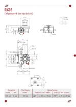
Configuration with short input shaft (VS) 5.3 kg 11.7 lbs Concentricity Precision Plate Planarity Precision Division Precision Single cycle (up to 12 stations) Double cycle (from 16 stations)
Open the catalog to page 9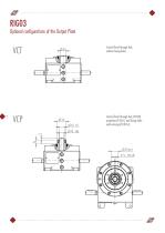
Optional configurations of the Output Plate Central fixed through hub, without fixing holes. Central fixed through hub, Ø15H8, projection Ø 32x15 and fixing holes with centring Ø 19h7x5.
Open the catalog to page 10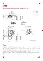
Configuration with reduction gear and self-braking motor (VLRA) 27 kg 59 lbs Notes • By reversing the direction of rotation of the input shaft, the direction of rotation of the output shaft is reversed, while the kinematic characteristics of the intermittent motion in standard mechanisms remain unchanged. • The 6 holes M6x15 on the output plate are in the position shown (pg.6 and 7) when the table is in the dwell period at one of the stations • The input shaft notches are in the position shown (pg.7) when the table is halfway through its dwell period • Some combinations of motors and reduction...
Open the catalog to page 11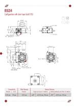
Configuration with short input shaft (VS) 16 kg 35 lbs Concentricity Precision Plate Planarity Precision Division Precision Single cycle (up to 12 stations) Double/quadruple cycle (from 16 stations)
Open the catalog to page 12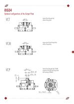
Optional configurations of the Output Plate Central fixed through hub, without fixing holes. Large central fixed through hub, without fixing holes. Central fixed through hub, Ø16H8, projection Ø 42x20 and fixing holes with centring Ø 20h8x5.
Open the catalog to page 13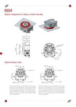
Optional configuration for ceiling or inverted mounting Optional reference holes Three dowel holes can be drilled in the output plate and in the table feet. The purpose of the hole in the output plate is to guarantee precise and repeatable assembly of the equipment. The two holes in the feet, on the other hand, allow precise positioning and make the table interchangeable. Three dowel holes can be drilled in the output plate and in the table ring. The purpose of the hole in the output plate is to guarantee precise and repeatable assembly of the equipment. The two holes in the feet, on the other...
Open the catalog to page 14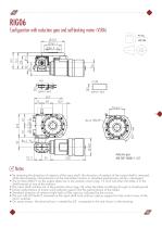
Configuration with reduction gear and self-braking motor (VLRA) 45 kg 100 lbs Notes • By reversing the direction of rotation of the input shaft, the direction of rotation of the output shaft is reversed, while the kinematic characteristics of the intermittent motion in standard mechanisms remain unchanged • The 6 holes M8x19 on the output plate are in the position shown (pg. 13 and 14) when the table is in the dwell period at one of the stations • The input shaft notches are in the position shown (pg.14) when the table is halfway through its dwell period • Some combinations of motors and reduction...
Open the catalog to page 15All COLOMBO FILIPPETTI catalogs and technical brochures
 SRP
SRP28 Pages
 Product Catalogue
19 Pages
 RIGS04 - RIGSD6 - RIGSO0
16 Pages
 SERVO ROLLER POSITIONER
12 Pages
 CF3
CF316 Pages
 H..S
H..S28 Pages
 RIGP
RIGP24 Pages
 IR1601 - IR1801 - IR2001
20 Pages
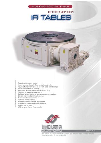
 IR1001 - IR1301
20 Pages
 RIG04 - RIG06 - RIG09
32 Pages
 INTERMITTENT MECHANISM
20 Pages
 Parallel oscillating drives
16 Pages
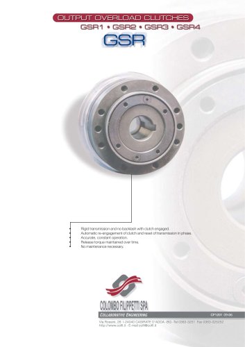
 Output overload clutches
6 Pages



Archived catalogs
 FRET SAW MACHINES "HOBBY 50"
2 Pages






- Rail conveyor
- Transport rail conveyor
- Horizontal conveyor
- Materials handling manipulator
- Chain conveyor
- Manipulator for industrial applications
- Handling manipulator
- Tool changer
- Index unit
- Electric manipulator
- Loading manipulator
- Lifting manipulator
- Rotary indexing table
- Cam indexer
- Rotary indexer
- Electric rotary indexing table
- Rotary manipulator
- Unloading manipulator
- Horizontal rotary indexing table
- Automatic tool changer