- Catalogs
- COLOMBO FILIPPETTI
- INTERMITTENT MECHANISM
INTERMITTENT MECHANISM
1 /20Pages

INTERMITTENT MECHANISM
1 /20Pages
Catalog excerpts

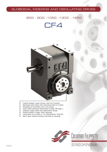
INTERMITTENT MECHANISM Compact housing. Possibility of mounting the unit in any plane. High precision positioning. Positive continuous motion control of moving masses. Fast transfer time and reduced pauses. Nitrided or hardened cams. Cam shaft located in taper roller bearings. Long-life lubrication. Worm geared motorisation directly mounted on housing. Built-in torque limiter clutch option. http://www.cofil.com - E-mail: cofil@cofil.com Via G. Rossini 26 - 24040 Casirate D’Adda Bg IT Phone +39 0363 3
Open the catalog to page 1
Technical data Rotary indexing table RIG. 04 VLRA Rotary indexing table IR201 VLRA Standard movements
Open the catalog to page 3
The units of measurement correspond with System International /Severity Index SI General tolerances of manufacture are conform to UNI – ISO 2768-1 UNI EN 22768- 1 Illustrations and drawings according to UNI 3970 (ISO 128-82). Method of projection of the drawings. COLOMBO FILIPPETTI may make any changes they feel necessary for the improvement of their products without advance notice. COLOMBO FILIPPETTI may change any market components and accessories mentioned in this catalogue as they feel necessary. This catalogue supersedes all previous issues
Open the catalog to page 4
MININDEX 1. MINIATURE INTERMITTENT MOTION ASSEMBLIES Miniature assemblies Standard configurations are normally a mechanical intermittent motion box complete with worm geared 3 phase asynchronous motor input. A microswitch assembly is used for stop/start cycle-on-demand operation in cam dwell period only. Housings are made of aluminium alloy, except IR201. The intermittent mechanisms Standard configurations are cam profiles which have symmetrical accel/decel phases and use modified sinusoidal motion law. Input rotational sense reversal produces corresponding output rotational sense reversal. Hence...
Open the catalog to page 5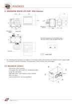
MININDEX 2. INDEXING DRIVE CF3 40P- VRA Version 44.5 Output shaft The shaft keyways are in the positions when the input shaft is in the mid-dwell of the cam Input shaft Index shaft By reversing the direction of rotation of the input shaft, the direction of rotation of the output shaft is reversed while the kinematic characteristics of the motion are unchanged. Aluminium alloy housing Conjugate flat cams with H.F. hardened profile Long life lubrication STM RMI 28 FL. Self braking motor reducer MEC 56 Motor Cam group/micro running operation Input Shaft
Open the catalog to page 6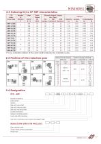
2.2 Indexing Drive CF 40P characteristics MININDEX CF3 Index Drive Code (*) one complete rotation of the input shaft produces two complete cycles.
Open the catalog to page 7
MININDEX3. INDEXING DRIVE CF4 50G -VRA Version Index shaft • By reversing the direction of rotation of the input shaft, the direction of rotation of the output shaft is reversed while the kinematic characteristics of the motion are unchanged. 3.1 Standard Version - Aluminium alloy housing - Globoidal cam with hardened profile - Long life lubrication - STM RMI 28 FL. Self braking motor reducer - MEC 56 Motor - Cam group/limit switch assembly for consent operation
Open the catalog to page 8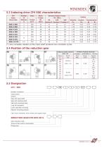
MININDEX «ffg3.3 Indexing drive CF4 50G characteristics v ' J CF4 Index Drive Code (*) One complete rotation of the input shaft produces two complete cycles.
Open the catalog to page 9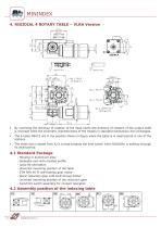
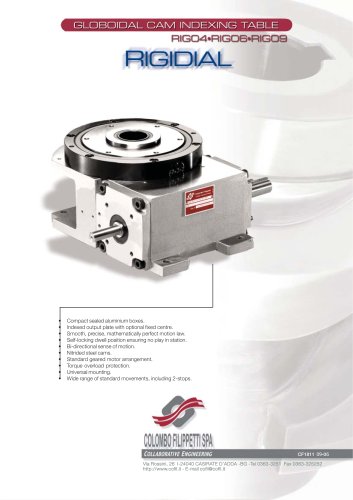
MININDEX 4. RIGIDIAL 4 ROTARY TABLE – VLRA Version By reversing the direction of rotation of the input shaft, the direction of rotation of the output shaft is reversed while the kinematic characteristics of the motion in standard mechanism are unchanged. The 6 holes M6X15 are in the position shown in figure when the table is in dwell period in one of the stations. The notch axis (viewed from A) is turned towards the limit switch when RIGIDIAL is halfway through its dwell period. Housing in aluminium alloy Globoidal cam with nitrided profile Long life lubrication Universal mounting position of the...
Open the catalog to page 10
MININDEX SERIES (*) One complete rotation of the input shaft produces two complete cycles..
Open the catalog to page 11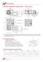
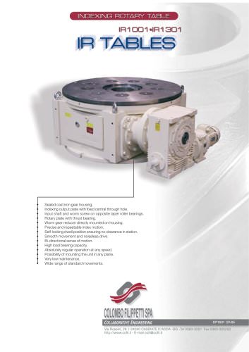
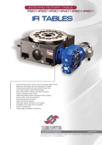
MININDEX 5. ROTARY INDEXING TABLES IR201 – VLRA Version h7 By reversing the direction of rotation of the input shaft, the direction of rotation of the output shaft is reversed while the kinematic characteristics of the motion are unchanged. The direction of rotation is as indicated in the sketch. Cylindrical cam case hardening Long life lubrication Universal mounting position of the table STM RMI 40 FI self-braking gear motor Worm reduction gear with built-torque limiter Universal mounting position of the reduction gear Cam/limit switch assembly for consent operation 5.2 Assembly positions of...
Open the catalog to page 12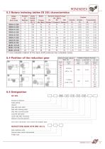
MININDEX IR201 Index Drive Code (*) one complete rotation of the input shaft produces two complete cycles.
Open the catalog to page 13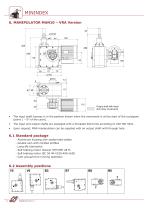
• The input shaft keyway is in the position shown when the movement is at the start of the cyclogram (point 1 - 0° of the cycle). • The input and output shafts are equipped with a threaded blind hole according to UNI ISO 9321. • Upon request, MAN manipulators can be supplied with an output shaft with through hole. 6.1 Standard package - Aluminium housing with sealed steel plates - Double cam with nitrided profiles - Long-life lubrication - Self braking motor reducer STM RMI 28 FL - Self braking motor IEC 56 4P-V230-400-Hz50 - Cam group/micro running operation Output shaft with linear and rotary...
Open the catalog to page 14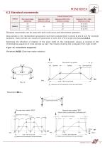
MININDEX 6.3 Standard movements Linear strokes [mm] SERIES Max input Angle [Degrees] Sequence A01U Without overlap Sequence B01U-01I.. Without overlap Sequence B01..-B02.. Without overlap Standard movements can be used with both continuous and intermittent operation. Stop periods in the represented cyclograms have been programmed in points 1 and 4 only for example purposes. Dwell periods can usually be positioned in each one of the single points 1,2,3,4,5,6. Reversing the direction of rotation of the input shaft on the manipulator causes a reversal of the chronological sequence of cycle periods...
Open the catalog to page 15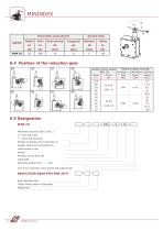
MININDEX SERIES 6.4 Position of the reduction gear 6.5 Designation -
Open the catalog to page 16
7. MICRO GROUPS In many applications that need the use of INDEX DRIVES a limit switch cam is used necessarily to stop the motor at every cycle end. When the application calls for stopping the motor at each cycle, either to prolong dwell times or to reverse the direction of rotation, a limit switch can be used for that purpose. The limit switch cams mounted on the cam shaft, are made in three standard shapes, each one suited to the type of limit switch used. Such cams are catalogued as shown below. • ATTENTION: the phase cam is not a safety device. Keyed to the opposite side of the reducer. 7.1...
Open the catalog to page 17All COLOMBO FILIPPETTI catalogs and technical brochures
 SRP
SRP28 Pages
 RIGIDIAL EN
40 Pages
 Product Catalogue
19 Pages
 RIGS04 - RIGSD6 - RIGSO0
16 Pages
 SERVO ROLLER POSITIONER
12 Pages
 CF3
CF316 Pages
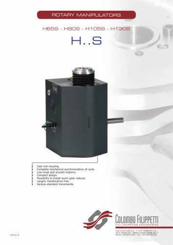 H..S
H..S28 Pages
 RIGP
RIGP24 Pages
 IR1601 - IR1801 - IR2001
20 Pages
 IR1001 - IR1301
20 Pages
 RIG04 - RIG06 - RIG09
32 Pages
 Parallel oscillating drives
16 Pages
 Output overload clutches
6 Pages


Archived catalogs
 FRET SAW MACHINES "HOBBY 50"
2 Pages


- Rail conveyor
- Transport rail conveyor
- Horizontal conveyor
- Materials handling manipulator
- Chain conveyor
- Manipulator for industrial applications
- Handling manipulator
- Tool changer
- Index unit
- Loading manipulator
- Electric manipulator
- Lifting manipulator
- Cam indexer
- Rotary indexer
- Electric rotary indexing table
- Rotary manipulator
- Unloading manipulator
- Automatic tool changer
- Horizontal rotary indexing table