H..S
1 /28Pages

H..S
1 /28Pages
Catalog excerpts

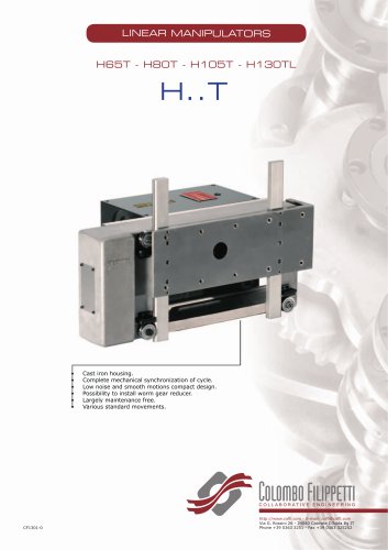
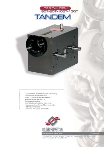
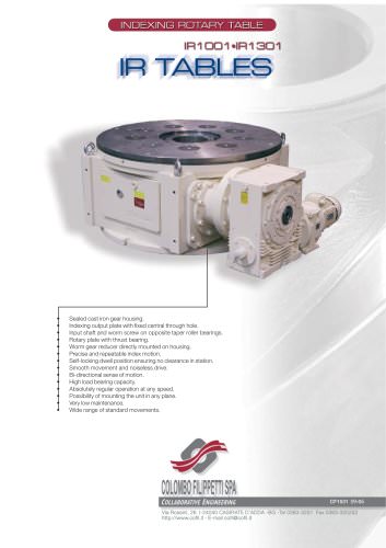
Cast iron housing. Complete mechanical synchronization of cycle. Low noise and smooth motions. Compact design. Possibility to install worm gear reducer. Largely maintenance free. Various standard movements. http://www.cofil.com - E-mail: cofil@cofil.com Via G. Rossini 26 - 24040 Casirate D’Adda Bg IT Phone +39 0363 3251 -
Open the catalog to page 1
INTERMICO manipulators of the H..S series are compactly designed devices with positive- locking, hardened and ground cams. A globoid cam and a plate cam serve pendulum gear serve as driving elements. The movements of the gripper arm follow a circular path. The device is available in the form of a lifting-stepping model or a lifting-oscillating model.
Open the catalog to page 3
Contents PAG 24. Slewing bearings ton request; obligatory for A1 movement The units of measurement correspond with System International /Severity Index SI General tolerances of manufacture are conform to UNI - ISO 2768-1 UNI EN 22768-1 Illustrations and drawings according to UNI 3970 (ISO 128-82). Method of projection of the drawings. All rights reserved. No part of this catalogue may be duplicated. COLOMBO FILIPPETTI may make any changes they feel necessary for the improvement of their products without advance notice. COLOMBO FILIPPETTI may change any market components and accessories...
Open the catalog to page 5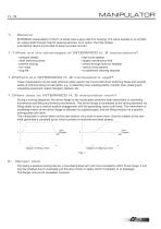
General INTERMICO manipulators of the H..S series have a gray cast iron housing. The cams operate in an oil bath. An output shaft through hole for passing services, is an option, the hole rotates. A protective device is provided to keep out water and dirt. 1.1 What are the advantages of INTERMICO H..S manipulators? - compact design - short switching times - positive locking - low noise - long life - high cycle speeds - largely maintenance-free - central through hole (on request) - various drive options - no additional indexing required 1.2 Where are INTERMICO H..S manipulators used? These manipulators...
Open the catalog to page 6
Application examples of INTERMICO H..S manipulators In many applications, you will find that, by using two or more arms with grippers, it is possible to load and unload simultaneously at high speed. By adding more dwell positions, it is also possible to perform other functions together with the loading and unloading operations. Fig. 2 INTERMICO manipulator as a workpiece feeder Fig. 3 INTERMICO manipulator as a transfer device Fig. 4 INTERMICO manipulator in an insertion system. It has an additional drive for the transfer movement of a conveyor belt.
Open the catalog to page 7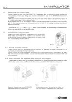
Selecting the right type In order to select the right type of INTERMICO H..S manipulator, it is not sufficient to simply calculate the mass moment of inertia and lifting load and then determine the size of the INTERMICO manipulator accordingly. In the case of cam-controlled manipulators, the ratio of the total inertial radius to the geometrical radius of the installed globoid gear is also a decisive factor. We recommend that you get our Technical Office to calculate the right type of INTERMICO manipulator for you. For this purpose, please use the questionnaire at the end of the catalog, enclosing...
Open the catalog to page 8
5.3 Instructions for trouble-free operation Elastic elements must be avoided at all costs in the drive train. Use only torsionally rigid elements. Use only hardened parallel pins to connect attachment devices, e.g. grippers. Screw fittings should be secured with a screw retention fluid. Regular stopping of the INTERMICO manipulator when in motion period should be avoided to prevent damage to the device. If an inching control facility is provided for setting operations or if frequent emergency stops are likely during the movement phase, this must be taken into account in the design. 6. Start -up All...
Open the catalog to page 9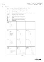
8. Models H60G INTERMICO manipulators are available in the following models: GS Manipulator driven directly via cam shaft GU Manipulator with reducing gear on cam shaft GU1 1 Manipulator with built-in worm gear and GU2 J free drive shaft GUF Manipulator with reducing gear and flange for mounting electric motors GUF1 1 Manipulator with built-in worm gear and GUF2 J flange for mounting electric motors GM Manipulator with gear motor GM1 1 Manipulator with built-in worm gear and GB Manipulator with transmission brake motor GB1 1 Manipulator with built-in worm...
Open the catalog to page 10
Mounting positions for external reducing gears The INTERMICO GS model manipulators can be equipped with external worm gears with a slipping overload clutch. By using different gear reductions, it is possible to obtain a range of 7 to 50 shifts per minute. The gears can be mounted in 16 different positions. When ordering, the following details are necessary in addition to the required mounting position: The transmission ratio of the worm gear or the number of cycles per minute performed by the manipulator in continuous operation The IEC dimensions of the motor flange, if the gear is to be supplied...
Open the catalog to page 11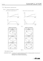
10. Movement sequences 10.1. Lifting-stepping model Movement sequence A1 Fig. 10 Other stations on request IMPORTANT: In the case of A1 movement sequences (rotation in extended position), the devices are supplied with an additional slewing bearing. (See page 19 for an additional slewing bearing)
Open the catalog to page 12
10.2. Lifting-oscillating model Movement sequence A1 IMPORTANT: In the case of A1 movement sequences (pivoting in extended position), the devices are supplied with an additional slewing bearing. (See page 19 for an additional slewing bearing)
Open the catalog to page 13
11. Determining the type designation The type designation of INTERMICO H..S manipulators is made up of alphanumeric groups as shown in the table below Series Number of stations (lifting-stepping) Angle of oscillation (lifting-oscillating) Stroke in mm _ Movement sequence _ 1 Plane with cam shaft _ 2 Plane with mounting holes_ 3 Plane with oil level gauge _ 4 Bottom plane after installation _ 5 Plane for mounting control cams_ Mounting position of external reducing gear Possible plane combinations 1 Plane with cam shaft 2 Plane with mounting holes Q T 3 Plane with oil level gauge __ 4...
Open the catalog to page 14All COLOMBO FILIPPETTI catalogs and technical brochures
 SRP
SRP28 Pages
 RIGIDIAL EN
40 Pages
 Product Catalogue
19 Pages
 RIGS04 - RIGSD6 - RIGSO0
16 Pages
 SERVO ROLLER POSITIONER
12 Pages
 CF3
CF316 Pages
 RIGP
RIGP24 Pages
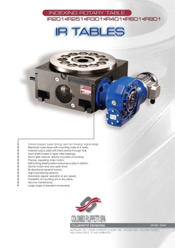
 IR1601 - IR1801 - IR2001
20 Pages
 IR1001 - IR1301
20 Pages
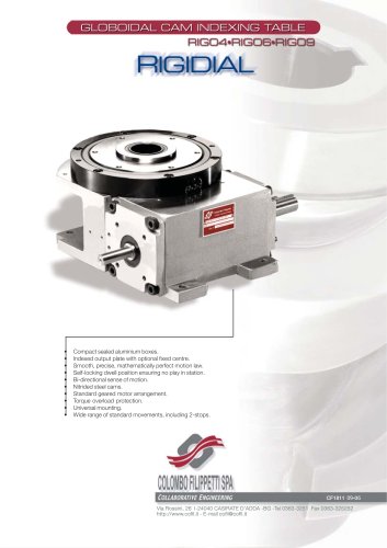
 RIG04 - RIG06 - RIG09
32 Pages
 INTERMITTENT MECHANISM
20 Pages
 Parallel oscillating drives
16 Pages
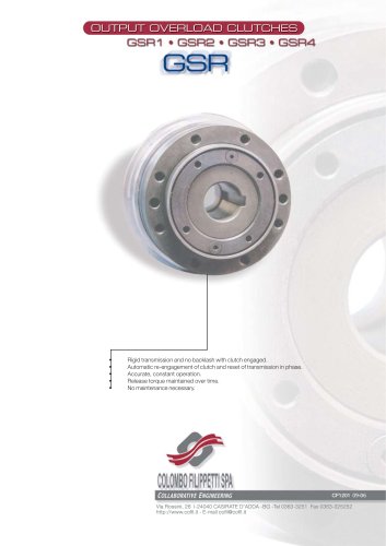
 Output overload clutches
6 Pages


Archived catalogs
 FRET SAW MACHINES "HOBBY 50"
2 Pages


- Transport rail conveyor
- Horizontal conveyor
- Materials handling manipulator
- Chain conveyor
- Manipulator for industrial applications
- Handling manipulator
- Tool changer
- Index unit
- Loading manipulator
- Electric manipulator
- Lifting manipulator
- Rotary indexing table
- Cam indexer
- Rotary indexer
- Electric rotary indexing table
- Rotary manipulator
- Unloading manipulator
- Automatic tool changer
- Horizontal rotary indexing table