
- Catalogs
- COLOMBO FILIPPETTI
- Colombo Filippetti - Rotary manipulators of the series MAN


Colombo Filippetti - Rotary manipulators of the series MAN

Colombo Filippetti - Rotary manipulators of the series MAN
The document details the MAN series rotary manipulators, which transform uniform rotating motion into linear and rotating intermittent movements. These manipulators are noted for their simple construction, compactness, and oil-bath lubrication, making them ideal for machine loading-unloading and assembly operations.
The manipulators come in five series: MAN 10, MAN 20, MAN 30, MAN 40, and MAN 50, each with distinct rotations and strokes. Tables specify standard rotations and linear strokes for each series. Specifications include types, reduction ratios, torque limiters, and assembly positions, along with motor types, sizes, and configurations.
These manipulators can function in continuous or intermittent modes, with options for one-way or oscillating output rotations. Synchronization with handled pieces is crucial, emphasizing electrical timing and safety.
Designations consist of alphanumeric groups indicating series, number of stations, angular stroke, linear stroke, movement sequence, version, cam helix direction, input shaft, and assembly positions. An example designation for series MAN 40 is provided.
Proper installation involves blocking the case against movement reaction forces and using clearance-free couplings to prevent premature wear. Maintenance access should be considered in application design.
Applications include loading and unloading on rotary tables and conveyors, with illustrations for different movement sequences.
The document adheres to System International units and UNI – ISO 2768-1 standards for general tolerances. Illustrations follow UNI 3970 (ISO 128-82) standards.
Tables provide dimensions for series MAN 10 to MAN 50, including overall dimensions and weight. Input shaft keyway positions and output shaft configurations are specified.
Static and dynamic load capacities are detailed for each series, covering radial, axial, over-turning, tangential, rotation, and lifting loads.
Precision data for linear stroke and rotation on radius are provided for each series.
Details on linear strokes, maximum angles, and movement sequences (A, B, C types) are provided, with diagrams and explanations of stop periods and dwell positions.
Various manipulator versions are described, including standard, special, and those with reduction gears. Directions of rotation and input shaft configurations are explained. Assembly positions are flexible due to "long-life" lubrication.
Information on using limit switches to control motor cycles, including cam shapes and microswitch units, is provided.
Details on reduction gear assembly positions and standard reduction gear motor dimensions are provided, with options for different motor and reduction gear configurations.
Oil-bath lubrication details are provided, including lubricant amounts for each series and maintenance instructions. A lubricant conversion table is included.
Includes overall dimensions for a fixing plate for the gripper arm.
Catalog excerpts

Since this is a positive drive machine, the gripper arm which may be installed moves all the time in its area. During ordinary operation it can be stopped only after: drive motor overload, operation of the safety clutch possibly installed or breakdown of mechanical parts. > 1.1 Description The MAN family manipulators, featuring a single cam globoidal and flat combined, can turn uniform rotating motion into an appropriate and ordered series of movements, linear intermittent and rotating intermittent (indexing version) or oscillating intermittent (oscillating version) of the output shaft on which...
Open the catalog to page 3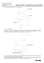
Oil plugs Input shaft Output shaft A BCDEF Fig. 1 1.5 Installation Access for maintenance operations must be provided for when designing an application with MAN manipulators. In addition, it is always best to block the case in the direction of the movement reaction forces so that the fastening screws are stressed only by traction forces (see F Fig. 2 ). > Fastening screws Reaction and reference plate Fig. 2 The use of clearance-free couplings and transmissions, both at the input and output points, is recommended in order to avoid premature wear caused by vibrations. To guarantee the output selected...
Open the catalog to page 4
Indexingrotary table Indexingrotary table Loading Unloading LoadingUnloading MAN MAN MAN A1 movements sequence - Rotation angle 120 - Linear stroke 85 mm Application: Loading and unloading pieces on a rotary table operated intermittently by an 8-station IR 301 Fig. 5 Manipulators with type Fig. 3 Manipulators with type ӓ B1 movements sequence - Oscillation angle 90 - Linear stroke 85 mm Application: Loading and unloading pieces on a rotary table operated intermittently by an 8-station Rig 06 Fig. 4 Manipulators with type > MAN Intermittent rotary conveyor belt MANCF3 B1 Ӕ movements sequence...
Open the catalog to page 5
2.3 Intermittent operation with reversal of input direction of rotation. The complete cycle which can only be with an oscillating output rotation, is carried out in two strokes. The first period, realised in a complete cycle of the cam, produces only half the cycle (from point 2.2 Intermittent operation with one-way input direction of rotation 1 to point 4 , going). The second period, realised in a complete cam cycle with reversed direction of rotation, produces the other half of the cycle, essentially repeating the first period in the opposite direction. (from point Exactly as for the continuous...
Open the catalog to page 7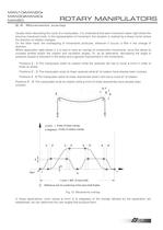
Usually when describing the cycle of a manipulator, it is understood that each movement starts right where the previous movement ends. In the representation of movement, this situation is marked by a sharp corner where the direction of rotation changes. On the other hand, the overlapping of movements produces, wherever it occurs, a fillet in the change of direction. Where application data allows it, it is best to have an overlap of consecutive movements, since this allows to increase strokes and/or the rotation and oscillation angles. Or, as an alternative, decreasing the angle of pressure causes...
Open the catalog to page 8
Series Precision of linear stroke h Precision of rotation on radius [mm] R=100 A [mm] MAN 10 0.10 0.080 MAN 20 0.12 0.070 MAN 30 0.13 0.050 MAN 40 0.14 0.035 MAN 50 0.15 0.030 >
Open the catalog to page 11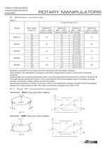
Tab. 6 Linear strokes [mm] Series Max. angle Sequence A01U A02U Sequence B01.. ֖ B02.. Sequence B01.. B02.. Sequence C01U ֖ C02U [degrees] w without overlap w without overlap with overlap without overlap 90 30 43 di (45) MAN 10 120 45 30 39 di (45) 45 180 20 35 di (45) 90 65 65 di (65) MAN20 120 65 45 60 di (65) 65 180 30 53di (65) 90 70 84 of (85) MAN30 120 85 70 81 of (85) 85 180 40 65 of (85) 90 70 95 of (110) MAN40 120 110 70 85 of (110) 110 180 50 61 of (110) 90 110 151 of (165) MAN50 120 165 110 138 of (165) 165 180 80 103 of (165) Standard movements can be used with both continuous and...
Open the catalog to page 12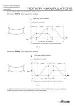
MAN50 > 5.3 Type CӔ movements sequence Stop period in Low position UpstrokeDownstroke Rotation Reversal 12341 Reference axis for positioning of the input shaft feather1 cycle = 360 of input shaftStart Fig. 18 Stop period in Low position DownstrokeUpstroke Rotation Reversal 12341 Reference axis for positioning of the input shaft feather1 cycle = 360а of input shaftStart Fig. 19 In addition to standard movement sequences and strokes, a great number of other sequences with linear strokes and special rotations can be obtained with MAN manipulators. 13 size="-3">
Open the catalog to page 14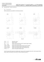
6.1 Versions MAN manipulators are available in the following versions. > Fig. 20 VS (---) Standard version VX (---) Special version VL (---) Version with long-shaft pre-set for reduction gear coupling VR (LR) Version with reduction gear VRP (LRP) Version with reduction gear pre-set for motor coupling VRA (LRA) Version with reduction gear and self-braking motor VMK (LMK) Version with reduction gear motor and brake clutch VRX (---) Version with special reduction gear Only for versions that require the reduction gear, whenever this is requested with built-in clutch torque limiting device, after...
Open the catalog to page 15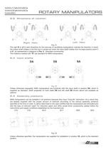
Right HelixLeft Helix Fig. 21 The right R or left L helix directions for the one-way or oscillating manipulators, indicate the direction in which the output shaft rotates in the first turn it carries out when the input shaft rotates from its base position point 1 at 0 ,.as represented in diagrams of Par. 5 . (Standard movements). The rotations marked with Г R are standard for MAN manipulators. > Fig. 22 Unless otherwise requested, MAN manipulators are furnished with the input shaft in position DA , which is supplied as standard. Shaft projected on both sides DS and left shaft SA shown above are...
Open the catalog to page 16
The manipulator can be supplied with the FC detection units with additional microswitches and cams. The illustrations below show the foreseen FC3 detection unit, which is made up of three microswitches with 3 cams capable of supplying three signals in certain positions of the movement cycle. If necessary, we can supply positions for the micro unit. All positions refer to the manipulator, not to the reduction gear. > BACD B ADC A B B C A C D D ADC C B AD B FC micro unit representation > B A A DC BD C Fig. 26 Assembly positions Tab. 8 Overall dimensions F FC Unit B C D A FC2 65 FC3 100 112 162...
Open the catalog to page 18All COLOMBO FILIPPETTI catalogs and technical brochures
 SRP
SRP28 Pages
 RIGIDIAL EN
40 Pages
 Product Catalogue
19 Pages
 RIGS04 - RIGSD6 - RIGSO0
16 Pages
 SERVO ROLLER POSITIONER
12 Pages
 CF3
CF316 Pages
 H..S
H..S28 Pages
 RIGP
RIGP24 Pages
 IR1601 - IR1801 - IR2001
20 Pages
 IR1001 - IR1301
20 Pages
 RIG04 - RIG06 - RIG09
32 Pages
 INTERMITTENT MECHANISM
20 Pages
 Parallel oscillating drives
16 Pages
 Output overload clutches
6 Pages
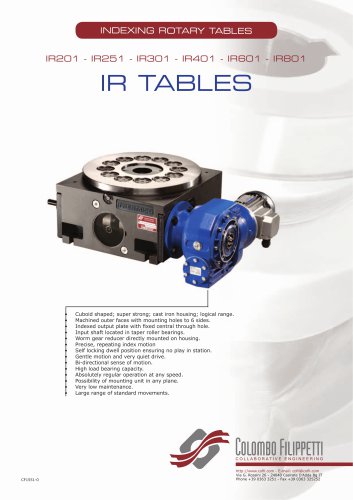

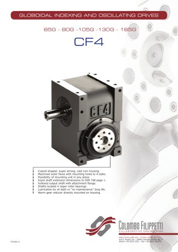


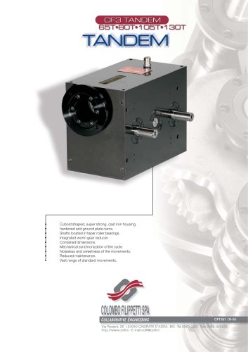
Archived catalogs
 FRET SAW MACHINES "HOBBY 50"
2 Pages






- Transport rail conveyor
- Horizontal conveyor
- Materials handling manipulator
- Chain conveyor
- Manipulator for industrial applications
- Handling manipulator
- Tool changer
- Index unit
- Electric manipulator
- Loading manipulator
- Lifting manipulator
- Rotary indexing table
- Cam indexer
- Rotary indexer
- Electric rotary indexing table
- Unloading manipulator
- Horizontal rotary indexing table
- Automatic tool changer