
- Catalogs
- COLOMBO FILIPPETTI
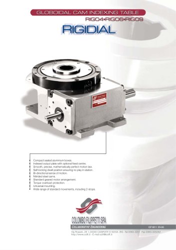
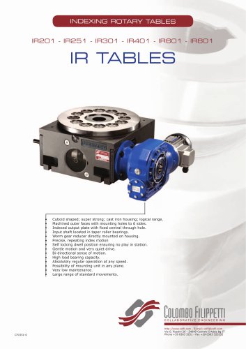
- Colombo Filippetti - Indexing Rotary Tables - Rigidal


Colombo Filippetti - Indexing Rotary Tables - Rigidal
Colombo Filippetti - Indexing Rotary Tables - Rigidal
The document outlines the specifications for a reduction gear system, including a universal mounting position, cam/limit switch assembly, and a globoidal cam with a left-hand helix profile. The cam features a hardened and ground profile, with various versions available (VS, VCT, VCP). The system includes a keyed camshaft projection on both ends (Style DS), different central through hole diameters for VCT and VCP versions, a double extended reduction gear worm shaft, and self-braking gearmotors from the STM RMI series.
Standard rotation directions are indicated by arrows, with shaft dimensions adhering to UNI-ISO 775 standards and key dimensions following BS 4235 ISO R773. The input shaft key position is specified for dwell time, and specific shaft dimensions are provided for limit switch operating cams.
The document describes optional versions (VS, VCT, VCP) with specific features and dimensions, including different hub and hole configurations, threaded holes, and interaxis alignments.
Detailed dimensions for various RIGIDIAL versions are provided, along with notes on reversing rotation direction and its effects. Technical features of motor-reducers may limit RIGIDIAL capabilities.
The package includes rotary indexing tables, globoidal cams, lubrication, and gearmotors, with various mounting positions and cam profiles available. A torque limiter and proximity switch are included.
Characteristics for RIGIDIAL 4, 6, and 9 tables are detailed, including the number of stops, dwell periods, torque values, coefficients, load capacities, and static forces.
The document provides various gear ratios and corresponding output specifications, along with power and torque values for different RMI series gearmotors.
A built-in clutch torque limiter with calibration option is included to prevent damage under accidental overloads, ensuring rigid transmission without slipping.
Long-life lubrication with ISO VG 150 mineral oil is specified, with certain mounting positions requiring no additional lubrication. Instructions for lubrication of reduction gears and related components are provided.
The limit switch cam assembly is designed to extend the mechanical cam dwell period or reverse the motor's rotational direction during the dwell period, allowing for a change from one-way indexed motion to oscillating index motion. The input shaft keyway is centrally placed in the cam's dwell period, with a reference notch indicating the position for the limit switch to trip. An aluminum plate supports the limit switch, and a pin on the input shaft head supports the cams, which are secured with grub screws. The pin length can be adjusted as needed.
The ordering code for the RIGIDIAL system is an alphanumeric combination specifying size, number of stations, index period, version, mounting position, input shaft type, and output hub type. For reduction gears, the code includes model, ratio, mounting position, worm shaft extension, and torque limiter. For self-braking motors, the code specifies size, power, number of poles, voltage, and frequency. An example code is provided for a specific configuration of the RIGIDIAL indexing table, reduction gear, and self-braking motor.
Catalog excerpts
Continuous camshaft rotation which is used in fast applications when the machine cycle is carried out in one revolution of the main shaft. Each single work operation is synchronised within a particular sector of main shaft rotation. This type of operation is indicated for machines whose motions are actuated only by mechanical drives. 2. Operation By electrical control which is used in all applications when a long dwell time is required owing to the length of the production times necessary. By this means of operation, stopping is controlled by a microcam mounted on the table input shaft. This...
Open the catalog to page 3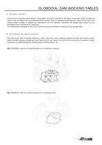
3. Danger areas Since this is a positive-action device, a tool plate with tools mounted on the table moves only within its area. Its motion may be halted only by switching off the driving motor or following break-downs in parts of the drive. The torque limiter is solely to protect the mechanism and not persons. Therefore, the danger area should not be accessed whilst the device is in operation. For maintenance operations, the motor must be switched off before crossing into the danger area. Fig. 2 RIGIDIAL used as an indexing table on an assembly machine. 4. Examples of applications The use of...
Open the catalog to page 4
6. Mounting instructions 7. Using the self-braking motor RIGIDIAL indexing tables can be mounted in any position. When mounting, the shafts of the device or plate should not be submitted to higher torque than prescribed. Mount the units in such a way that they are anchored rigidly to the base. Set the position using two pins. The thread of the anchor screws should be treated with anaerobic material to prevent easy unscrewing. Check the presence of lubricant: appropriate labels are affixed on RIGIDIAL tables to indicate when filling was effected. When mounted, check the position at which the limit...
Open the catalog to page 5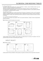
9. Commissioning All RIGIDIAL tables are supplied with Long-Life lubrication on delivery, and are therefore ready to go into operation. The lubricant used is ISO VG 150 mineral oil. The type and presence of lubricant in the box is in any case indicated by means of a yellow label glued to it. The torque limiter is calibrated despatch. It may be set for the application advised or to the maximum permitted for the assembly, if application advice, is lacking. 10. Maintenance RIGIDIAL indexing tables have no special requirements with regard to maintenance, but they must be inspected regularly for leakage...
Open the catalog to page 6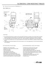
12. Overall dimensions RIGIDIAL 4 Fig. 7 VLRA Version > Self braking motorMax. IEC 71b B14 notchViewed from "A"Scale 2:1 Max ReducerRMI 40 F1 NOTES: By reversing the direction of rotation of the input shaft, the direction of rotation of the output shaft is reversed while the kinematic characteristics of the intermittent motion in standard mechanisms remains unchanged. The 6 holes M6x15 are in the position shown in fig. 7 when the table is in dwell period in one of the stations. The notch axis (Viewed from A) is turned towards the limit switch when RIGIDIAL is halfway through its dwell period....
Open the catalog to page 7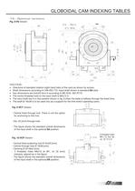
10.5 NOTES: Directions of standard rotation (right-hand helix of the cam) as shown by arrows. Shaft dimensions according to UNI-ISO 775. Input shaft shown is standard DA style Key dimensions are 5x5x25 form A according to BS 4235 ISO R773. The centre threaded hole on the input shaft is M5x12.5 . The input shaft key is in the position shown in fig. 8 when the table is halfway through the dwell time. The shaft 16x39 is to be used only as a support for the limit switch operating cams. Fig. 9 VCT Version - Central fixed through hub. There is not the option for anchoring to this hub. - Dia. 25 [mm]...
Open the catalog to page 8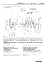
14. Overall dimensions RIGIDIAL 6 Fig. 11 VLRA Version > Viewed from "A"Scale 2:1 notch N 5 holes M6x9on P.C.D. 238Nа 6 holes M8x19 Self braking motorMax. IEC 80b B14 A Max ReducerRMI 50/F1 14 M6 NOTES: By reversing the direction of rotation of the input shaft, the direction of rotation of the output shaft is reversed while the kinematic characteristics of the intermittent motion in standard mechanisms remains unchanged. The 6 holes M8x19 are in the position shown in fig. 11 when the table is in dwell period in one of the stations. The notch axis (Viewed from A) is turned towards the limit switch...
Open the catalog to page 9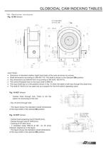
15. Optional versions Fig. 12 VS Version > N 5 holes M6x9on P.C.D. 238 NOTES: Directions of standard rotation (right-hand helix of the cam) as shown by arrows. Shaft dimensions according to UNI-ISO 775. The shaft is shown in the standard DA position Key dimensions are 6x6x40 form A according to BS 4235 ISO R773. The centre threaded hole on the input shaft is M8x19. The input shaft key is in the position shown in fig. 12 when the table is half-way through the dwell time. The shaft И 16x53 is to be used only as a support for the limit switch operating cams. Fig. 13 VCT Version SA position. - Central...
Open the catalog to page 10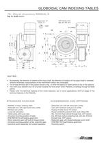
16.- Overall dimensions RIGIDIAL 9 Fig. 15 VLRA Version > Viewed from "A"Scale 2:1notch Self braking motorMax. IEC 90L B14 N 5 M8 x 15 A Max ReducerRMI 85/F3 NOTES: By reversing the direction of rotation of the input shaft, the direction of rotation of the output shaft is reversed while the kinematic characteristics of the intermittent motion are unchanged. The 6 holes M10x25 are in the position shown in fig. 13 when the table is in dwell period in one of the stations. The notch axis (Viewed from A) is turned towards the limit switch when RIGIDIAL is halfway through its dwell period. Please note,...
Open the catalog to page 11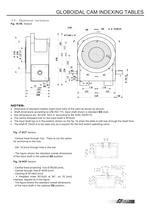
17.- Optional versions Fig. 16 VS Version > N5 M8 x 15 NOTES: Directions of standard rotation (right-hand helix of the cam) as shown by arrows. Shaft dimensions according to UNI-ISO 775. Input shaft shown is standard DA style. Key dimensions are 8x7x50 form A according to BS 4235, ISOR773. SA position. The centre threaded hole on the input shaft is M10x22 . The input shaft key is in the position shown on the fig. 16 when the table is half-way through the dwell time. The shaft И 16x53 is to be used only as a support for the limit switch operating cams. Fig. 17 VCT Version - Central fixed through...
Open the catalog to page 12All COLOMBO FILIPPETTI catalogs and technical brochures
 SRP
SRP28 Pages
 RIGIDIAL EN
40 Pages
 Product Catalogue
19 Pages
 RIGS04 - RIGSD6 - RIGSO0
16 Pages
 SERVO ROLLER POSITIONER
12 Pages
 CF3
CF316 Pages
 H..S
H..S28 Pages
 RIGP
RIGP24 Pages
 IR1601 - IR1801 - IR2001
20 Pages
 IR1001 - IR1301
20 Pages
 RIG04 - RIG06 - RIG09
32 Pages
 INTERMITTENT MECHANISM
20 Pages
 Parallel oscillating drives
16 Pages
 Output overload clutches
6 Pages



Archived catalogs
 FRET SAW MACHINES "HOBBY 50"
2 Pages






- Rail conveyor
- Transport rail conveyor
- Horizontal conveyor
- Materials handling manipulator
- Chain conveyor
- Manipulator for industrial applications
- Handling manipulator
- Tool changer
- Index unit
- Electric manipulator
- Loading manipulator
- Lifting manipulator
- Cam indexer
- Rotary indexer
- Electric rotary indexing table
- Rotary manipulator
- Unloading manipulator
- Horizontal rotary indexing table
- Automatic tool changer