Catalog excerpts
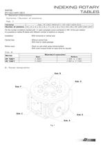
Series Standard execution > Cam Rollers IR 1001 360 65 e 80 IR 1301 420 80 e 100 >
Open the catalog to page 3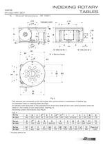
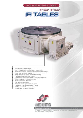
4. Overall dimensions IR 1001 G Indicator notch AMJ C H W D T1 B K1 N1M1 Q O VLP L1 Z U U V1U1ISE1 DIN 332 Bl. 2DIN 332 Bl. 2 Nְ 4 Service Holes KB1 H1I1J1 S1 NR FE > Fig. 2 The reducers are connected on the input shaft with conical lockers in substitution of feather key. For standard holes on indexing plate see Pag7. An Idicator notch executed on the opposite front of the input shaft will be in the vertical position when the table is in the middle of cam dwell period. See Pag 10. Anchoring system informations. See Pag.8. Tab. 6 SeriesA B C D k6 E F G H7 H H7 I J K L M N IR 1001 960 550 345...
Open the catalog to page 5
5.Overall dimensions IR 1301 GH Indicator notch W DAMJ T1 Q V M1N1B OV1U1ISE1 P CFE Z U DIN 332 Bl. 2 U DIN 332 Bl.2 Nְ 4 Service holes K NR B1 H1I1J1 > Fig 3 The reducers are connected on the input shaft with conical lockers in substitution of feather key. For standard holes on indexing plate see Pag7. An Idicator notch executed on the opposite front of the input shaft will be in the vertical position when the table is in the middle of cam dwell period. See Pag 10. Anchoring system informations. See Pag.8. Tab. 7 SeriesA B C D k6 E F G H7 H H7 I J K M N IR 1301 1330 650 495 110210710 450...
Open the catalog to page 6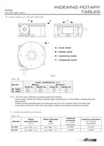
Load coefficients [kN] Series Static Dynamic Axial C > oa Radial C > or Axial C > a Radial C > r IR 1001 > Plate flatness (B) Indexing precision Series Plate concentricity (2 cycles) [degrees] [mm] [mm] (1 cycle) [degrees] Indexing precision >
Open the catalog to page 7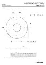
8.Standard drilling scheme of indexing plate > Fig. 5 N.B. IR table is represented in the middle of a dwell in a station . Tab. 10 > Series A C HOLES NE HOLES N谰 IR 1001 700 20H7 x 25 4 M20 x 32 12 > IR 1301 1020 20H7 x 25 4 M24 x 40 12 On demand, can be supplied, INDEXING TABLE with special holes. > 7 size="-1">
Open the catalog to page 8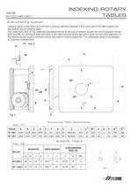
Indexing tables of this series are built with a centring diameter obtained in the lower side of the table aligned with the rotation axis of indexing plate. Two radial slots, also on the underside and perpendicular to the axis of rotation, enable the use of precision blocks (DIN 6322/B). By centring at least one block a very rigid torsional anchorage and a quick and accurate alignment of the table to the structure is obtained without any need of control equipment. The rectangular plate is not supplied by Colombo Filippetti SPA. > 20Vew X
Open the catalog to page 9
11. Mounting positions > A C B D E F Fig. 8 Standard mounting position of IR tables is Position A . The B , C , D , E , F positions are optional and must be explicitly requested at the time of order. In A mounting position the lubrication of IR 1001 and IR 1301 tables is by oil. In B , C , D , E , F mounting positions lubrication is by synthetic grease. The table in E and F positions can anchored only with frontal holes 11.Motorizations COLOMBO FILIPPETTI SPA can also supply the motorization and overload protection systems for this rotary table. Other than the different possible solutions,...
Open the catalog to page 10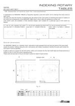
CT cam for push operated limit switch with roller D4B 1171-DIN43694 FORM B cam for lever operated limit switch with roller D4B 1111- IN43694 FORM A/B cam for proximity limit switch E2E2 - X2B1 o TLE X5BI-G CENELEC (EN 50008) > 1520 CL > 1530 CM > 152530
Open the catalog to page 11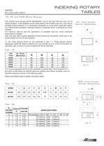
13. FC and FCR Micro Groups This simple micro groups permit identification only of the fact that the cam is in a certain position. If this position be the dwell period, the IR table must be in any one of perhaps several stations. It is sometimes necessary to know which particular station e.g. tables where oscillation between stations is required which is achieved by motor reversal. For machine start-up and for prevention of possible over-run, extra positional information is needed. One may also need several separate control signals for processes which are to be synchronised with the IR cam...
Open the catalog to page 12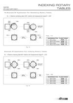
TABLEROT. 180POS. A MICROSWITCH FUNCTIONS 1 Micro Stop > POS. A 2 Micro Over stroke > POS. A 3 Micro Stop > POS. B 4 Micro Over stroke > POS. B CAM 2CAM 3 CAM 1CAM 4 CAM 4 CAM 1CAM 2 CAM 3 TAB. MICRO AXIS R = 0.75 TABLEROT. 90а AXIS MICROSWITCH FUNCTIONS 1 Micro Stop POS. A 2 Micro Stop POS. B 3 Micro Stop POS. C 4 Micro Stop POS. D
Open the catalog to page 13
15. Lubrication IR 1001 and IR 1301 long-life lubricated tables are delivered already filled with oil on the ground of mounting position. In B , C , D , E , F mounting positions lubrication is by synthetic grease. In A mounting position the lubrication of IR 1001 and IR 1301 tables is by oil bath, only the rollers are lubricated by conveyance of lubricant. The recommended lubricant is ISO VG 320 mineral oil or similar. Lubrication frequency, unless leakage or external pollution have occurred, is as shown in Tab. 19 and depends on the temperature achieved by the oil under standard operating...
Open the catalog to page 14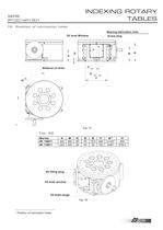
16.Position of lubrication holes > Screw plug EOil level Window CD B HBearing lubrication hole A 1) FBilateral oil drain G + Fig. 15 Tab. 22 > Series A B C D E F G 1) H IR 1001 300 38080 55 18,54803x120а485 > IR 1301 350 45080 55 35 7634x90 579,5 > Oil filling plug Oil level window Oil drain plugs Fig. 16 > 1) Position of lubrication holes. > 14 size="-2">
Open the catalog to page 15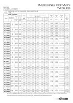
TABLE CODE Dynamic torque (at output) cycles/min M Static torque Coeff. of Accel. Coeff. of Trasm. Numberand type of roller Angle of displace Angle of Dwell Mu [daN m] Number of Series > On demand INDEXING TABLE with special movement can be supplied. The IR Rotary table denoted by (*) with a complete rotation of the input shaft produce two complete cycles of the output shaft: "displacement-dwell, displacement-dwell". >
Open the catalog to page 16
18. Designation > The ordering code of the IR INDEXING TABLES is composed of an alphanumerical combination according to the chart here below. IR TABLE Series Type of roller N of stations Displacement angle Version Face with cam shaft Face with indexing plate Face with clamping holes Face with oil filling plug (long-life lubrication L V) Constructive shape or bottom face after assembly Reduction gear assembly position (not for VSS and VSL) > REDUCTION GEAR Type Version Reduction ratio Technical characteristics > Torque limiter Type : Torque limiter setting : daNm Coupling type: Allowable...
Open the catalog to page 17All COLOMBO FILIPPETTI catalogs and technical brochures
-
SRP
28 Pages
-
RIGIDIAL EN
40 Pages
-
Product Catalogue
19 Pages
-
RIGS04 - RIGSD6 - RIGSO0
16 Pages
-
SERVO ROLLER POSITIONER
12 Pages
-
CF3
16 Pages
-
H..S
28 Pages
-
RIGP
24 Pages
-
IR1601 - IR1801 - IR2001
20 Pages
-
IR1001 - IR1301
20 Pages
-
RIG04 - RIG06 - RIG09
32 Pages
-
INTERMITTENT MECHANISM
20 Pages
-
Parallel oscillating drives
16 Pages
-
Output overload clutches
6 Pages
Archived catalogs
-
FRET SAW MACHINES "HOBBY 50"
2 Pages

