- Catalogs
- COLOMBO FILIPPETTI
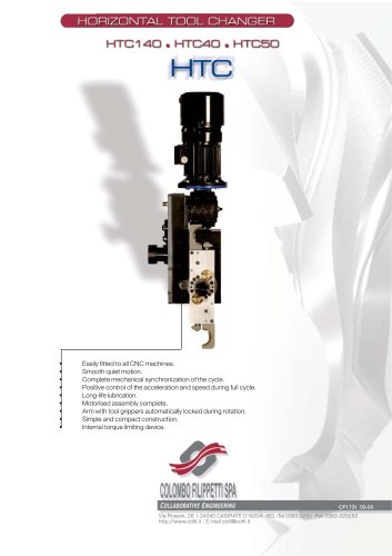
- Colombo Filippetti - High Speed Cam Toolchangers - HTC
Colombo Filippetti - High Speed Cam Toolchangers - HTC
1 /16Pages
Colombo Filippetti - High Speed Cam Toolchangers - HTC
1 /16Pages
Catalog excerpts

1. Home or park position 2. Engaging of Tools (Arm rotation 90а) 3. Extraction of Tools (output linear movement) 4. Exchange of Tools (arm rotation 180) 5. Insertion of Tools (return linear movement) 6. Release of Tools (arm rotation 90а) >
Open the catalog to page 3
4.Direction of rotation of the gripper arm The STANDARD direction of rotation designation D, as shown below The OPTION designation S is for counter-clockwise output shaft rotation to produce gripper-arm motions in the opposite direction. Fig. 3 Direction of rotation > 5. Danger area Since we are dealing with a repetitive movement mechanism and positive coupling, the gripper arm moves only within its action range. The tool changer mechanism can be stopped only after: overload of the drive motor, reaction of the torque limiting coupling, failure of an internal component or power outage. Personnel...
Open the catalog to page 5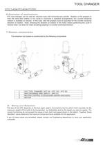
6.Examples of applications HTC tool-changers can be used for machine tools with horizontal-axis spindle. Rotation of the grippers to hold the tools (first rotation in the cycle) is clockwise in standard arrangements, but counter-clockwise rotation is available on request. In this case also the grippers must be specified for the counter-clockwise direction of rotation. Note: reversing the direction of rotation of the motor means performing the cycle in reverse order, but does not mean actuating gripping in a counter-clockwise direction. 7.System components The extraction tool system is constructed...
Open the catalog to page 6
9. Using a self-braking motor A self-braking motor is used to stop the mechanism during a dwell provided at the end of each tool change cycle. It will remain there until the machine control calls for another tool change cycle. To facilitate adjustment and synchronization during installation or for maintenance manual brake release to allow manual drive shaft rotation, is provided. An alternative to self-braking motors, is inverter or vector controlled. These have been used successfully. These motors have no mechanical parts to wear, and allow precies regulation of speed. Another type of motor...
Open the catalog to page 7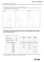
12. Mounting positions of the reduction gear HTC tool changers can be delivered complete with a self-braking gearmotor or simply with a worm gear reducer mounted in one position in respect to the HTC .HTC 140 HTC 40 HTC 50 Fig. 7 Postition of the reducer HTC assemblies can be prepared for alternative systems other than standard applications, for example combinations of: coupling, clutch brake, speed variators, etc. Upon request, these can also be supplied directly by COLOMBO FILIPPETTI. 13. Technical characteristics Tab.: 2 > Max tool weight (kg) 10 15 25 Max stroke extraction (mm) 60 110 165...
Open the catalog to page 8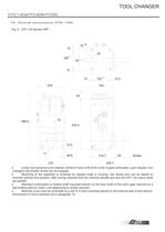
14. Overall dimensions HTC 140 Fig. 8 - HTC 140 Version VRP 16 > H7 15 25 165 > 0.1 30 > 0.05 15 15 150 > 0.1 15.5 235 195 54 486.5 75 432.5 72.5 17 M16 219.7 60 Stroke 210 338.7 > Linear tool extraction and insertion stroke of tools is 60 (mm) is the longest achievable; upon request, tool changers with shorter stroke can be supplied. Mounting of the assembly is achieved by tapped holes in housing, two dowel pins can be added to maintain precise final position, after having checked that the machine spindle axis and the HTC 140 output shaft are parallel. Standard motorization is (hollow shaft...
Open the catalog to page 9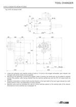
HTC140 HTC40 HTC50 Fig. 9 HTC 40 Version VLRA 15 3 > 0.0 5 M16 > H7 16 27 > 0.1 138 15 15 230 > 0.1 15 66 184 68 130 325 431 379 80 17 157 110 Stroke 318 455 > Linear tool extraction and insertion stroke of tools is 110 (mm) is the longest achievable; upon request, tool changers with shorter stroke can be supplied. Mounting of the assembly is achieved by tapped holes in housing, two dowel pins can be added to maintain precise final position, after having checked that the machine spindle axis and the HTC 40 output shaft are parallel. Standard motorization is (hollow shaft mounted directly on the...
Open the catalog to page 10
Fig. 10 HTC 50 Version VLRA M16 x22 35 18 > 0.05 H7 33 16 220 160 > 0.1 25 25 269 > 0.1 25 392.5 100 205 88 170 450 112.5 550 483 200 97 17 200.5 Stroke165 620.5 > Linear tool extraction and insertion stroke of tools is 165 (mm) is the longest achievable; upon request, tool changers with shorter stroke can be supplied. Mounting of the assembly is achieved by tapped holes in housing, two dowel pins can be added to maintain precise final position, after having checked that the machine spindle axis and the HTC 50 output shaft are parallel. Standard motorization is (hollow shaft mounted directly...
Open the catalog to page 11
15. Characteristics of output motion PRECISION OF OUTPUT MOTION Rotation 180 б0.05 [degrees] Linear stroke 110/60 0.20 [mm] Repeatability ѱ 0.03 [ -- ] Coplanarity 0.05 [mm] Concentricity 0.05 [mm] Fig. 11 16. Mounting and use of limit switch cams > Fig. 12 - Overall dimenstions of complete FC3 assembly Model and manufacturer of the multiple precision limit switch Balluff. BNS 543-B 03 R 12-61-12, or, EUCHNER SN 3-R 12-502 > As already described in section 21 the cams are mounted in such way as to actuate the limit switches that comand: 1)The dwell of the HTC in position end of cycle 2)The release...
Open the catalog to page 12
17. Description of the gripper arm 18. Overall dimensions The tool changer gripper arm consists of a central aluminium structure with terminal tool grippers of hardened steel. Tool gripping and release are obtained by means of a spring-operated mechanism actuated by the rotation of the arm. The latter, in turning, engages or disengages the grippers from the tools when these are in exchange position. While in motion, an irreversible mechanical type safety interlocking device enters automatically into operation and prevents accidental opening of the tool gripper. The gripper arm is attached to...
Open the catalog to page 13
20. Designations of the HTC tool changer The designation of the HTC assemblies consist of sets of alphanumerical characters as illustrated in the chart below. Please refer to this chart when ordering, to avoid misunderstandings and delays in deliveries. HTC 40 - O - 90 - 60 - D - VLRA > - Size series - Spindle axis (O=horizontal) - Rotation for change arm form park (90) - Shank extraction stroke (110 / 60) - Direction of rotation of the change arm (D=clockwise, S=counter-clockwise) - Version - With assembled arm gripper (BPH) EXAMPLE OF DESIGNATION > HTC 40 tool changer for machine tool with...
Open the catalog to page 15All COLOMBO FILIPPETTI catalogs and technical brochures
 SRP
SRP28 Pages
 RIGIDIAL EN
40 Pages
 Product Catalogue
19 Pages
 RIGS04 - RIGSD6 - RIGSO0
16 Pages
 SERVO ROLLER POSITIONER
12 Pages
 CF3
CF316 Pages
 H..S
H..S28 Pages
 RIGP
RIGP24 Pages
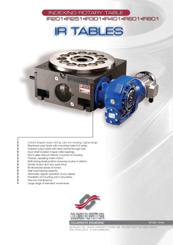
 IR1601 - IR1801 - IR2001
20 Pages
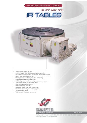
 IR1001 - IR1301
20 Pages
 RIG04 - RIG06 - RIG09
32 Pages
 INTERMITTENT MECHANISM
20 Pages
 Parallel oscillating drives
16 Pages
 Output overload clutches
6 Pages


Archived catalogs
 FRET SAW MACHINES "HOBBY 50"
2 Pages


- Rail conveyor
- Transport rail conveyor
- Horizontal conveyor
- Materials handling manipulator
- Chain conveyor
- Manipulator for industrial applications
- Handling manipulator
- Loading manipulator
- Index unit
- Electric manipulator
- Lifting manipulator
- Rotary indexing table
- Cam indexer
- Rotary indexer
- Electric rotary indexing table
- Unloading manipulator
- Rotary manipulator
- Automatic tool changer
- Horizontal rotary indexing table