Catalog excerpts
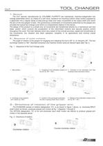
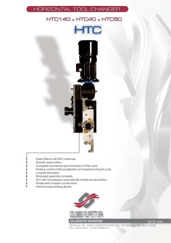
2.- Sequence of cycle motions The angle of rotation of the gripper for engaging and releasing the tool is 90 or, on demand, 60а. The tool exchange rotation is 180. Standard extraction and insertion stroke varies as relevant taper (See Tab.1). Fig. 1 - Sequence of the Tool Change cycle. > 1- General The CUT devices manufactured by COLOMBO FILIPPETTI are mechanical, machine-independent tool change assemblies which, by means of a cam drive, transform an incoming uniform rotary motion supplied by a gearmotor into a regular series of stop-and-go linear and rotary movements of the output shaft...
Open the catalog to page 4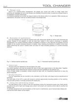
4.- Danger area Since it is a positive-action arrangement, the gripper arm moves only within its range. Apart from switching-off, stoppage can occur only owing to an overload of the drive motor, to action by a torque limiter or to breakdown of some internal part. It is therefore essential not to enter the range of action of the device while it is in operation. When carrying out maintenance, the power must be cut before access to the danger area. > Outside diameterExtractionstrokeof the grippers Fig. 3 - Danger area 5.- Examples of applications CUT tool-changers can be used for machine tools...
Open the catalog to page 5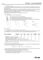
The tool changers come in the following versions: 12.- Maintenance CUT assemblies require very little maintenance. Check the box regularly for oil leakage, always a sign of malfunctioning of the assembly or wear of the seals. If any is noticed, proper maintenance should identify and eliminate the cause. When carrying out routine servicing, and in any case after 8'000 hours of operation, the CUT assembly gripper shaft should be checked for backlash; if necessary, the whole assembly should be overhauled. Always ensure that there is unrestricted free airflow for motor cooling purposes, and...
Open the catalog to page 7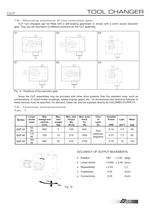
15.- Mounting positions of the reduction gear. CUT tool changers can be fitted with a self-braking gearmotor or simply with a worm screw reduction gear. They can be mounted in 6 different positions on the CUT assembly. D1 D3 D4 S1 S3 S4 Fig. 9 - Positions of the reduction gear Since the CUT assemblies may be provided with other drive systems than the standard ones, such as combinations of clutch-brake couplings, speed change gears, etc., all dimensional and technical features of these devices must be specified. On demand, these can also be supplied directly by COLOMBO FILIPPETTI. 16.-...
Open the catalog to page 8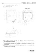
17. - Overall dimensions CUT 31 Fig. 11 - CUT 31 Version VS > The linear 85-mm tool extraction and insertion stroke is the longest achievable; on demand, tool changers with a shorter stroke can be supplied. > Mounting of the assembly is achieved by the use of the 4 slots in the standard plate, plus two pins added to locate precise final position after having checked that the machine spindle axis and the CUT 31 output shaft are parallel. > Machine cycle operation is controlled by a set of at least 3 limit switches which are operated by limit switch cams attached to the CUT input shaft. > 7...
Open the catalog to page 9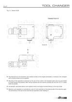
The linear 85-mm tool extraction and insertion stroke is the longest achievable; on demand, tool changers with a shorter stroke can be supplied. > Mounting of the assembly is achieved by the use of the 4 slots in the standard plate, plus two pins added to locate precise final position after having checked that the machine spindle axis and the CUT 31 output shaft are parallel. > As standard, self brake electric worm geared motors are flange mounted directly on the input shaft. > Machine cycle operation is controlled by a set of 3 limit switches on the external side of the reduction gear. The...
Open the catalog to page 10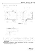
18.- Overall dimensions CUT 41 Fig. 13 - VS Version > The linear 110-mm tool extraction and insertion stroke is the longest achievable; on demand, tool changers with a shorter stroke can be supplied. Օ Mounting of the assembly is achieved by the use of the 4 slots in the standard plate, plus two pins added to locate precise final position after having checked that the machine spindle axis and the CUT 41 output shaft are parallel. Cycle operation must be assisted by a set of at least 3 limit switches which receive the signals from limit switch cams attached to the CUT input shaft. > 9...
Open the catalog to page 11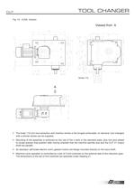
The linear 110-mm tool extraction and insertion stroke is the longest achievable; on demand, tool changers with a shorter stroke can be supplied. Mounting of the assembly is achieved by the use of the 4 slots in the standard plate, plus two pins added to locate precise final position after having checked that the machine spindle axis and the CUT 41 output shaft are parallel. Օ As standard, self brake electric worm geared motors are flange mounted directly on the input shaft. Machine cycle operation is controlled by a set of 3 limit switches on the external side of the reduction gear. The...
Open the catalog to page 12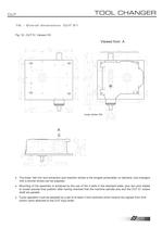
The linear 165-mm tool extraction and insertion stroke is the longest achievable; on demand, tool changers with a shorter stroke can be supplied. Օ Mounting of the assembly is achieved by the use of the 4 slots in the standard plate, plus two pins added to locate precise final position after having checked that the machine spindle axis and the CUT 51 output shaft are parallel. Cycle operation must be assisted by a set of at least 3 limit switches which receive the signals from limit switch cams attached to the CUT input shaft. > 11 size="-1">
Open the catalog to page 13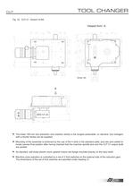
The linear 165-mm tool extraction and insertion stroke is the longest achievable; on demand, tool changers with a shorter stroke can be supplied. > Mounting of the assembly is achieved by the use of the 4 slots in the standard plate, plus two pins added to locate precise final position after having checked that the machine spindle axis and the CUT 51 output shaft are parallel. > As standard, self brake electric worm geared motors are flange mounted directly on the input shaft. > Machine cycle operation is controlled by a set of 3 limit switches on the external side of the reduction gear....
Open the catalog to page 14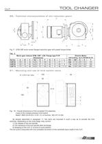
20.- Technical characteristics of the reduction gears Fig.17 - STM CBF worm screw flanged reduction gear with preset torque limiter. Tab. 2Worm gear reducer STM. CBF LCB. Flange type F1/P Electric Motor Dimensions > Self braking - 4p-V 230/400-Hz 50 Series A B C Dxl E F G H I L IEC kW O X Y CBF40 106 69 49 9x30 78 10859 10 57 7 63b 0.18 235 123140 CBF50 125 93 60 9x30 97 13469 10 69 9 71b 0.55 270 138160 CBF70 175 116 66 9x30 127 16593 10 88 17.5 80c 0.95 295 156200 21.- Mounting and use of limit switch cams. > N 3 off 6.5 dia. holes 321 Fig. 18 - Overall dimensions of the complete FC3...
Open the catalog to page 15All COLOMBO FILIPPETTI catalogs and technical brochures
-
SRP
28 Pages
-
RIGIDIAL EN
40 Pages
-
Product Catalogue
19 Pages
-
RIGS04 - RIGSD6 - RIGSO0
16 Pages
-
SERVO ROLLER POSITIONER
12 Pages
-
CF3
16 Pages
-
H..S
28 Pages
-
RIGP
24 Pages
-
IR1601 - IR1801 - IR2001
20 Pages
-
IR1001 - IR1301
20 Pages
-
RIG04 - RIG06 - RIG09
32 Pages
-
INTERMITTENT MECHANISM
20 Pages
-
Parallel oscillating drives
16 Pages
-
Output overload clutches
6 Pages
Archived catalogs
-
FRET SAW MACHINES "HOBBY 50"
2 Pages


