CF3
1 /16Pages

CF3
1 /16Pages
Catalog excerpts

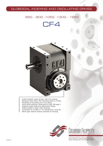
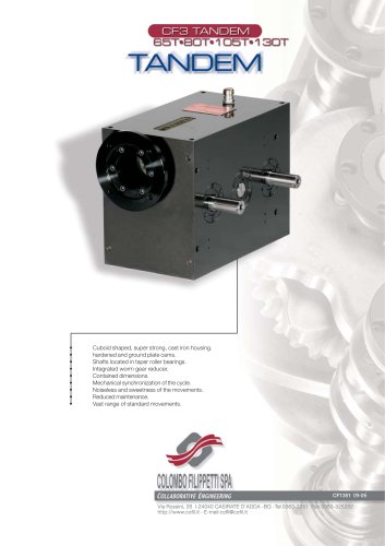
PARALLEL OSCILLATING DRIVES 65P-80P-105P-130P Prism-shaped sealed cast iron housing Outer surfaces machined, with support on 6 sides. Possibility of mounting housing in all positions. Parallel shafts projecting in input and output. Roller bearings on opposite taper roller shafts. Oil-bath lubrication. Worm gear reducer splined directly to housing. Precise repeatable index motion. Self locking in dwell and zero backlash. Smooth and shock-free movement Bidirectional sense of motion. http://www.cofil.com - E-mail: cofil@cofil.com Via G. Rossini 26 - 24040 Casirate D’Adda Bg IT Phone +39 0363
Open the catalog to page 1
CF3 OSCILLATING DRIVE Contents PAG The units of measurement correspond with System International /Severity Index SI General tolerances of manufacture are conform to UNI - ISO 2768-1 UNI EN 22768-1 Illustrations and drawings according to UNI 3970 (ISO 128-82). Method of projection of the drawings. All rights reserved. No part of this catalogue may be duplicated. COLOMBO FILIPPETTI may make any changes they feel necessary for the improvement of their products without advance notice. COLOMBO FILIPPETTI may change any market components and accessories mentioned in this catalogue as they feel necessary. This...
Open the catalog to page 3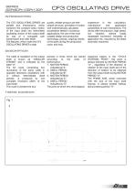
CF3 OSCILLATING DRIVE INTRODUCTION The CF3 OSCILLATING DRIVES are parallel axis mechanisms, which transform the constant rotary motion of the input shaft into intermittent oscillating motion of the output shaft by way of a conjugate cam transmission and roller feeler. The features, which make the CF3 OSCILLATING DRIVES a high DESCRIPTION The width of oscillation of the output shaft is known as "ANGULAR STROKE" and is indicated by the letter "H". The full cycle, comprising two revolutions of the same width in opposite directions (oscillation) with or without intermediate dwell periods, is produced...
Open the catalog to page 4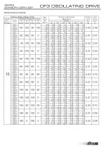
CF3 OSCILLATING DRIVESPECIFICATIONS OSCILLATING DRIVE CODE
Open the catalog to page 5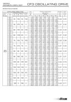
CF3 OSCILLATING DRIVESPECIFICATIONS OSCILLATING DRIVE CODE
Open the catalog to page 6
CF3 OSCILLATING DRIVESPECIFICATIONS OSCILLATING DRIVE CODE
Open the catalog to page 7
CF3 OSCILLATING DRIVESPECIFICATIONS OSCILLATING DRIVE CODE
Open the catalog to page 8
ASSEMBLY The CF3 OSCILLATING DRIVES can be assembled on four different ways, regardless of the mounting position. The type of assembly depends on the direction of rotation of the motion input and output shafts. If the CF3 OSCILLATING DRIVE is viewed from the output shaft side, "Side B", it can be seen that: 1. The input shaft can rotate clockwise, in wich case it is marked "D", or anti-clockwise, in which case it is marked "S". 2. If motion period "A" only is considered, the output shaft can rotate clockwise, and is marked "D" , or anti-clockwise, and is marked "S". Motion period "C" always rotates...
Open the catalog to page 9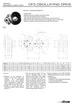
CF3 OSCILLATING DRIVE DRIVE COMPONENTS - Parallel shaft - Separate and pre-coupled cam/follower units - Cam hub with hollow shaft and keyway - High-strength alloy steel cams with hardened , ground contours - Follower hub with central through hole and flange mount on both sides. - High load capacity with special yoke-mounted cam followers. Notes • Reversal of the direction of rotation of the input shaft also reverses the chronological sequence of the cycle periods. This is equivalent to crossing the Timing diagram from right to left. • Keyway "T" of the cam hub is positioned halfway along indexing period...
Open the catalog to page 10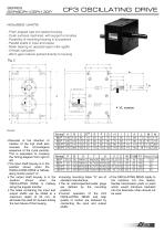
CF3 OSCILLATING DRIVE HOUSED UNITS - Prism-shaped cast iron sealed housing. - Outer surfaces machined, with support on 6 sides - Possibility of mounting housing in all positions - Parallel shafts in input and output - Roller bearing on opposite taper roller sgafts - Oil-bath lubrication - Worm gear reducer splined directly to housing Fig. 3 • Housing mounting holes "S" are of standard manufacture. • The oil inlet/inspection/outlet plugs are defined by the mounting position. • Correct operation of the CF3 OSCILLATING DRIVE and high quality of motion are obtained by connecting the input and output shafts...
Open the catalog to page 11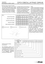
side with input shaft side with output shaft side with mounting hole side with oil plugs lower side after mounting IDENTIFICATION NUMBER The identification number of the OSCILLATING DRIVES is made up in accordance with the chart. The mounting positions in versions VR, VRP , VRM and VRA , is specified in the paragraph "REDUCER MOUNTING POSSIBILITIES" cycle periods_ side with input shaft -side with output shaft side with mounting holes side with oil plugs _ lower side after mounting
Open the catalog to page 12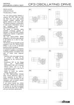
CF3 OSCILLATING DRIVE REDUCER MOUNTING POSSIBILITIES The CF3 OSCILLATING DRIVES in versions VR, VRP, VRM and VRA are fitted with worm gear speed reducers suitably selected and splined directly to the input shaft. This system presents a combination of rigid power trabsmission and a very compact motor- driven OSCILLATING DRIVE unit. The range of reduction ratios available produces speeds of between 14 and 200 RPM, thereby meeting the majority of application requirements. The CF3 OSCILLATING DRIVE designed for the worm gear reducer to be splined on, is the VL long-shaft version. The reducer can...
Open the catalog to page 13
Ito create] in movement with the times Products Cam Mechanisms and special products Compact double spherical cam mechanism for mechanical automation Combination of flat cam and globoidal profiled cam Globoidal cam mechanism with four synchronized intermittent movements. Bilateral outputs. Mechanism with different cams producing seven synchronized intermittent and oscillating the culture of precision Flat cam with conjugate profiles
Open the catalog to page 16All COLOMBO FILIPPETTI catalogs and technical brochures
 SRP
SRP28 Pages
 RIGIDIAL EN
40 Pages
 Product Catalogue
19 Pages
 RIGS04 - RIGSD6 - RIGSO0
16 Pages
 SERVO ROLLER POSITIONER
12 Pages
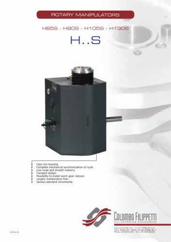 H..S
H..S28 Pages
 RIGP
RIGP24 Pages
 IR1601 - IR1801 - IR2001
20 Pages
 IR1001 - IR1301
20 Pages
 RIG04 - RIG06 - RIG09
32 Pages
 INTERMITTENT MECHANISM
20 Pages
 Parallel oscillating drives
16 Pages
 Output overload clutches
6 Pages


Archived catalogs
 FRET SAW MACHINES "HOBBY 50"
2 Pages


- Rail conveyor
- Transport rail conveyor
- Horizontal conveyor
- Materials handling manipulator
- Chain conveyor
- Manipulator for industrial applications
- Handling manipulator
- Tool changer
- Index unit
- Loading manipulator
- Electric manipulator
- Lifting manipulator
- Rotary indexing table
- Cam indexer
- Rotary indexer
- Electric rotary indexing table
- Rotary manipulator
- Unloading manipulator
- Automatic tool changer
- Horizontal rotary indexing table