

Worm Gear Units
Worm Gear Units
The installation of worm gear units requires stable fastening to prevent vibrations, checking the correct rotation direction, and protection from weather conditions. Long storage may necessitate seal replacement. Proper cooling and lubrication are essential, and specific mounting positions must be adhered to. A gradual start-up is recommended to avoid immediate maximum load application.
Performance specifications are based on specific mounting positions. Applications that could be hazardous, involve high inertia, or occur in extreme environments require consultation with technical services. The maximum torque should not exceed twice the nominal torque.
Reducers are supplied with either synthetic or mineral oil, depending on size. Regular oil level checks and replacements are necessary, especially for sizes 110-130. Special considerations are required for extreme temperatures, including the use of special oil seals and ensuring motors are suitable for low temperatures.
The service factor depends on load type, start-up frequency, and daily operating time. Load types are categorized as uniform, medium, or heavy, with specific applications listed for each. The moment of inertia should be considered, and technical service should be consulted if necessary.
Standard motor mounting positions are B3/A unless specified otherwise. For vertical placements, consult with technical services for critical applications. For non-standard positions, contact the Technical Service.
Details on terminal board positioning are provided, but specific configurations are not included in the summary.
The document lists various versions of the CRV and CMRV series, including CRV-E, CMRV, CMRV-F, CMRV-E, and CMRV-FL.
The document provides a detailed list of components for the CRV-CMRV series, including housing, worm wheel, worm screw, output and input shaft covers, bearings, oil seals, and O-rings.
The CRV-CMRV series features include lightweight aluminum housing for sizes 025-090, cast iron housing for sizes 110-130, high transmissible torque, reliability, and noiseless operation.
Details on product identification codes are provided, explaining the significance of each part of the code, such as motor type, flange type, reduction ratio, and size.
The document includes detailed dimensions for reducer sizes 030-130, specifying measurements for various parts and configurations.
Performance data for the CRV-CMRV series is provided, including input power, size, and torque specifications. The importance of considering the service factor in reducer selection is emphasized.
Details on the output flange position scheme are included, with specific dimensions for size 025 reducers.
Specifications for torque arm and output shaft dimensions are provided, including single and double shaft configurations.
Dimensions and configurations for the CRR-CMRR combined reducer series are detailed, including motor mounting positions and overall dimensions.
The document provides detailed specifications for reducers and motors, including performance metrics such as speed (n1=1400 1/min), power (P1 in kW), and torque (M2 in Nm). Various models and configurations are listed, with specific attention to the service factor, which is crucial for selecting the appropriate reducer size.
The document outlines the procedure for mounting an electric motor, emphasizing the importance of cleaning the motor shaft, removing and replacing the motor key, and fitting components like the bush, pinion, washer, and oil seal. It highlights the need for quality motors to ensure smooth operation without vibrations or noise.
Standard mounting positions are specified as B3, with instructions to consult technical services for non-standard positions. The document stresses the importance of considering the service factor in reducer selection.
Tables provide detailed performance data for various reducer models, including gear ratios, power, and torque. The data is crucial for understanding the capabilities and limitations of each model.
Dimensions for different reducer sizes are provided, including overall dimensions and specific measurements for components like the output flange and input shaft. This information is essential for ensuring compatibility with other system components.
The document highlights the main features of the CRB-CMRB series, such as lightweight aluminum alloy cases, high torque transmission, and reliable, noiseless operation. It also provides a product type identification guide to help users select the appropriate model based on their needs.
This document provides detailed technical specifications and performance data for the CRB-CMRB series of reducers, including dimensions, input and output parameters, and performance metrics. It is intended for use in selecting the appropriate reducer size based on specific application requirements.
The document outlines the overall dimensions for various models in the CRB-CMRB series, including CRB-S, CMRB-S, CRB-A, CMRB-A, CRB-V, and CMRB-V. Key dimensions such as input shaft, output hole, and weight are provided for each model.
Detailed performance tables are included, showing input power (Kw), output speed (n2 in r/min), and torque (M2 in n·m) for different sizes and ratios. The document emphasizes the importance of considering the service factor when selecting a reducer.
Information on CRRB-CMRRB combined reducers is provided, including dimensions and performance data. The document specifies standard types and notes that unless otherwise specified, the "A" version is supplied.
Dimensions for accessories such as torque arms and output shafts (single and double) are included. Charts provide detailed measurements for each size category.
The document repeatedly highlights the necessity of accounting for the service factor in reducer selection to ensure optimal performance and longevity.
The document concludes with contact details for CMR Srl, including address, phone, fax, and email, for further inquiries or support.
Catalog excerpts

Riduttori e Motoriduttori vite senza fine Worm gear units >
Open the catalog to page 1
INSTALLAZIONEAPPLICAZIONI CRITICHE LUBRIFICAZIONE FATTORE DI SERVIZIO ACCOPPIAMENTI MOTORE VERSIONI SERIE CMRV E CRV Caratteristiche principali Dimensione e ingombri riduttori grandezza 030-130 Prestazioni CRV-CMRV Schema flange di uscita Dimensione e ingombri riduttori grandezza 025 Vite senza fine a doppia sporgenza Predisposizione Braccio di reazione Dimensione alberi di uscita singolo (DZ), doppio (SZ) SERIE COMBINATI CRR-CMRR Dimensione e ingombri riduttori CRR-CMRR Prestazioni CRR-CMRR RIDUTTORI CON PRECOPPIE CMRP Dimensione e ingombri riduttori CMRP Combinazioni PR-CMRV MONTAGGIO MOTORE...
Open the catalog to page 2
Per linstallazione del riduttore Ҩ consigliabile seguire le indicazioni elencate: Il fissaggio sulla macchina deve essere stabile per evitare vibrazioni. ֖Prima del montaggio del gruppo sulla macchina verificare il corretto senso di rotazione dellalberodi uscita del riduttore.ҖQuando possibile proteggere il riduttore dallirraggiamento solare e dalle intemperie. ҖIn caso di lunghi periodi di stoccaggio (4/6 mesi) se lanello di tenuta non Ҩ immerso nel lubrifi-cante contenuto allinterno del gruppo si consiglia la sua sostituzione in quanto la gomma potreb- be essersi incollata allҒalbero o aver...
Open the catalog to page 3
(*) intesa come sovraccarico istantaneo dovuto ad avviamenti a pieno carico, frenature, urti ed altre cause soprattutto dinamiche. > (*) intended for momentary overloads due to starting at full load, braking, shocks or other causes, in particular dynamic causes. >
Open the catalog to page 4
QuantitР olio (in litri) Oil quantity (in liter) Oil quantity (in liter) Taglia25304050637590110130 Size Precoppie PR63718090Quantit olio (in litri) > Piazzamento - Position B3 0,020,040,080,150,30,55134,5 > Piazzamento - Position B3 0,050,070,150,16 > Piazzamento - Position B8 0,020,040,080,150,30,5512,23,3 > Piazzamento - Position B8 0,050,070,150,16 > Piazzamento - Position B6-B7 0,020,040,080,150,30,5512,53,5 > Piazzamento - Position B6-B7 0,050,070,150,16 > Piazzamento - Position V5 0,020,040,080,150,30,55134,5 > Piazzamento - Position V5 0,050,070,150,16 > Piazzamento - Position V6 0,020,040,080,150,30,5512,23,3...
Open the catalog to page 5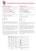
A-B-C frequenza di avviamento: avv/ora (*) > Il fattore di servizio f.s. dipende dalle condizioni di funzionamen-to sottoposte ad un riduttore. Per una corretta selezione del fattore di servizio piֹ adeguato occorre considerare i seguenti parametri: tipo del carico della macchina azionata: ֖durata di funzionamento giornaliero: ore/giorno ( ) The service factor (f.s.) depends on the operating conditions the reducer is subject to. To correctly select the most suitable service factor, it is necessary to consider the following parameters: type of load of the application: A-B-C ֖start-up frequency:...
Open the catalog to page 6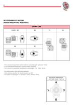
6 ACCOPPIAMENTI MOTORE MOTOR MOUNTING POSITIONS > CMRV - B3B6V5V6 B8B7 Per le posizioni di piazzamento verticali verificare quanto detto nelle applicazioni critiche.֖Se non diversamente specificato le posizioni standard sono B3/A. Per le posizioni di piazzamento non previste occorre rivolgersi al ns. Servizio Tecnico. ֖For vertical position, check with critical application.Unless otherwise specified, the standard positions are B3/A. ֖For positions not envisaged, it is necessary to call our Technical Service. POSIZIONE MORSETTIERA TERMINAL BOARD POSITION
Open the catalog to page 7
Tipo di motore applicabile Suitable type of motor SZ: a doppio albero di uscita, DZ: con un solo albero di usci-ta, senza sigla per uscita con foro di accoppiamento SZ : two-way output shaft, DZ : single output shaft, no markӔ:output with coupling hole Tipo di flangia di uscita, senza sigla flangia assente Output flange type: no markӔ: no flange E: per vite a doppia sporgenza, senza sigla per vite standard E: for double extension worm shaft, no markӔ: for standardworm screw. Rapporto di riduzione Reduction ratio Grandezza Size Sigla prodotto CMRV: con flangia di ingresso, CRV: senzaflangia di...
Open the catalog to page 10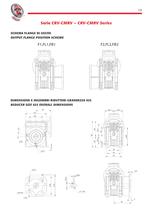
SCHEMA FLANGE DI USCITA OUTPUT FLANGE POSITION SCHEME > DIMENSIONE E INGOMBRI RIDUTTORI GRANDEZZA 025 REDUCER SIZE 025 OVERALL DIMENSIONS >
Open the catalog to page 14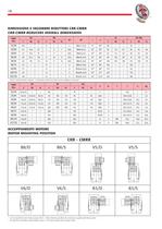
Taglia XAXBXLXN (H8)FFBFLFFBFLFFBFLFFBFL Size XCXE 1 > 140//15//6M12x21 (n.4)4522,5а255//180// > 40/50 e 40/63 fornibili a richiesta. - Combination 40/50 and 40/63 can be subblied on demand. Taglia XOXPXQFFBFLFFBFLFFBFL Size bb > 1 ftt > 1 Kg > ח Se non specificato viene fornita posizione B3/S. - Unless otherwise specified, the product are supplied with B3/S position. Per posizione morsettiera vedere tabella a pag. 6. - For motor position refer to page 6 table. size="-1">
Open the catalog to page 19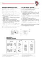
Per un corretto montaggio del pignone sullalbero del motoreelettrico occorre seguire le seguenti istruzioni:a)Pulire accuratamente lҒalbero del motore elettrico.b)Togliere la linguetta del motore della sede. c)Montare la boccola (6) sullalbero motore secondo lҒorienta-mento indicato nello schema. Per facilitare il montaggio si pu riscaldare la boccola a circa 70/80 C.d)Montare la nuova linguetta (4) fornita a corredo di quella pre-cedentemente tolta.e)Montare il pignone (1) adottando gli stessi accorgimentidescritti nel punto (c).f) Montare la rondella (2) e serrare tramite la vite (3). g)Togliere...
Open the catalog to page 23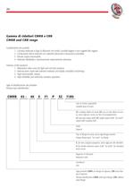
Tipo di motore applicabile Suitable type of motor SZ: a doppio albero di uscita, DZ: con un solo albero di usci-ta, senza sigla per uscita con foro di accoppiamento SZ : two-way output shaft, DZ : single output shaft, no markӔ:output with coupling hole Piede Support Tipo di flangia di uscita, senza sigla flangia assente Output flange type: no markӔ: no flange E: per vite a doppia sporgenza, senza sigla per vite standard E: for double extension worm shaft, no markӔ: for standardworm screw Rapporto di riduzione Reduction ratio Grandezza Size Sigla prodotto CMRB con flangia di ingresso, CRB senza...
Open the catalog to page 27
FLANGIA DI USCITA ALBERO DI ENTRATA FORO DI USCITA Taglia OUTPUT FLANGE INPUT SHAFT OUTPUT HOLE PESO Size AGG > 1 G > 2 HILLHNN > 1 N > 2 XER WEIGHT XAXBXCXLXNXOXPD > 1 b > 1 t > 1 fDbt Kg 30 2062,555584630653950302M6x9 (n.4)5150,5666850 7809310,214516,31 45 307465685545654950352M6x14 (n.4)7260,59987608,511011412,518(19)620,82,4 50 3081,58174,565509454,568383M6x9 (n.4)8185129907010,512316518M625(24)828,33 63 4599,5120937963907075455M8x17 (n.8)1008613715011510,517518620,5M625(28)828,36 85 50124135112988513094,5110643,5 M10x18 (n.4) 1381081651761521320525828M8351038,311 > Note - Notes: 1) Per posizione...
Open the catalog to page 28All CMR Group catalogs and technical brochures
 Cmr story
4 Pages
 Ceramics Plant Plastic Parts
70 Pages
 Micro-Castings
6 Pages
 Cmr Group
30 Pages


- Machining service
- Machining
- Conveyor roller
- Precision machining
- Straight-toothed gear
- Slip-on conveyor roller
- Metal pulley
- Forging
- Metal forging
- Plastic conveyor roller
- Groove pulley
- Helical-toothed gear
- Casting
- Steel pulley
- Cast iron pulley
- PVC conveyor roller
- Transmission gear
- Steel forging
- Custom-made gear
- Ferrous metals casting