
- Catalogs
- CMB Cilindri
- ISO 6020

ISO 6020

ISO 6020
Overview
This document relates to the ISO 6020/2 standard, which governs hydraulic cylinders used in industrial hydraulic systems. It establishes technical specifications, design criteria, testing protocols, and quality assurance measures to ensure consistent and reliable cylinder performance.
1. Scope and Application
The standard applies to hydraulic cylinders with defined dimensions and performance characteristics, including both single-acting and double-acting types. It specifies their intended use within hydraulic systems.
2. Technical Specifications
- Dimensions and Tolerances: Precise dimensional requirements for components such as piston diameter, rod diameter, stroke length, and mounting interfaces are defined to ensure interchangeability and proper assembly.
- Materials: Material specifications include steel grades and surface treatments aimed at durability and corrosion resistance.
- Pressure Ratings: Maximum operating pressures and safety factors are established to guarantee safe operation under expected loads.
- Sealing Systems: Seal types and installation requirements are specified to prevent leakage and contamination.
3. Design and Construction
- Design principles focus on structural integrity to withstand mechanical stresses and pressure.
- Surface finish standards for piston rods are outlined to minimize wear and friction.
- Guidance on mounting arrangements and accessory compatibility is provided.
4. Testing and Quality Assurance
- Hydrostatic Testing: Procedures to verify cylinder strength and detect leaks under pressure.
- Dimensional Inspection: Methods to measure critical dimensions ensuring compliance with tolerances.
- Performance Testing: Functional tests under load and stroke conditions to assess operational reliability.
5. Marking and Documentation
Cylinders must be marked with identification codes, manufacturer details, and pressure ratings. Each unit should be accompanied by documentation including test reports and certificates of compliance.
6. Recommendations and Best Practices
- Installation and maintenance guidelines to extend service life.
- Handling and storage instructions to prevent pre-use damage.
- Compatibility considerations with hydraulic fluids and system components.
7. Tables and Data Summary
The document includes tables listing standard sizes, pressure ratings, and dimensional limits, serving as references for design and procurement to ensure standardization.
Critical Information Highlights
- Defined maximum operating pressures with safety margins.
- Material grades and surface finish standards critical for durability.
- Dimensional tolerances essential for interchangeability.
- Mandatory testing procedures for quality assurance.
- Marking requirements for traceability and compliance.
Additional Document Notes
Some versions of the document were found corrupted or unreadable, containing fragmented or non-standard characters, which prevented extraction of detailed technical data. It is recommended to use a clean, properly formatted version for full analysis.
Company Information
The document references CMB S.r.l., an Italian manufacturer specializing in pneumatic and hydraulic cylinders, providing contact details for technical support and inquiries.
Summary
This structured summary captures the essential elements of the ISO 6020/2 standard for hydraulic cylinders, including specifications, design, testing, and best practices, facilitating compliance, design decisions, and quality control in hydraulic system applications.
Catalog excerpts

HYDRAULIC CYLINDERS
Open the catalog to page 1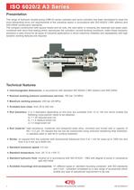
ISO 6020/2 A3 Series Presentation The range of hydraulic double-acting CMB A3 series cylinders and servo-cylinders has been developed to meet the most demanding drive unit requirements of the industrial sector in accordance with ISO 6020/2 (1991 edition) and DIN 24554 construction standards. The compact construction with square heads and tie rods, the care taken in choosing the materials and seals used, combined with strict final testing which reproduces the cylinders normal working conditions, make these hydraulic actuators a valid choice for all types of industrial applications in which maximum...
Open the catalog to page 2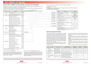
ISO 6020/2 A3 Series How to order a CMB A3 series cylinder compliant with ISO 6020/2 When issuing the order for the cylinder, provide the following information: The CMB A3 series cylinders compliant with ISO 6020/2 standards are provided with an identification code which describes the construction specifications in a non-ambiguous way. To make up the code for the order, follow the code diagram set out below and insert the letters identifying the various features of the desired cylinder in the sequence given below. Cylinder ordering code To ISO 6020/2 standards with magnetic sensors To ISO 6020/2...
Open the catalog to page 3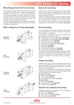
ISO 6020/2 A3 Series Mountings choice for the A3 series Side foot mounting The complete range of ISO 6020/2 A3 series cylinders manufactured by CMB offers 17 different mounting types capable of meeting most working requirements. On the following pages the general criteria to be used in choosing the type and space requirements of the mounting types for single rod and double rod cylinders with their corresponding accessories are described. As regards special applications, our Technical Department is at your complete disposal for the construction of cylinders to particular requirements. Cylinders...
Open the catalog to page 4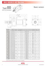
Basic version Unless otherwise specified, all dimensions are given in millimetres. Hydraulic and pneumatic cylinders
Open the catalog to page 5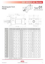
ISO 6020/2 A3 Series Rectangular front flange * Max 200 bar ** Max 150 bar *** Max 120 Bar Unless otherwise specified, all dimensions are given in millimetres. Hydraulic and pneumatic cylinders
Open the catalog to page 6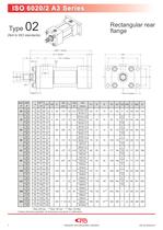
Rectangular rear flange * Max 200 bar ** Max 150 bar *** Max 120 Bar Unless otherwise specified, all dimensions are given in millimetres. Hydraulic and pneumatic cylinders
Open the catalog to page 7
ISO 6020/2 A3 Series Side foot Unless otherwise specified, all dimensions are given in millimetres. Hydraulic and pneumatic cylinders
Open the catalog to page 8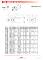
Head trunnion Unless otherwise specified, all dimensions are given in millimetres. Hydraulic and pneumatic cylinders
Open the catalog to page 9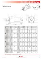
Unless otherwise specified, all dimensions are given in millimetres. Hydraulic and pneumatic cylinders
Open the catalog to page 10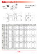
Intermediate fixed trunnion * Specify the dimension in case of order. Unless otherwise specified, all dimensions are given in millimetres. Hydraulic and pneumatic cylinders
Open the catalog to page 11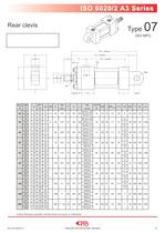
ISO 6020/2 A3 Series Rear clevis Unless otherwise specified, all dimensions are given in millimetres. Hydraulic and pneumatic cylinders
Open the catalog to page 12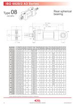
Rear spherical bearing Unless otherwise specified, all dimensions are given in millimetres. Hydraulic and pneumatic cylinders
Open the catalog to page 13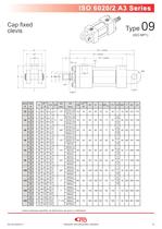
ISO 6020/2 A3 Series Cap fixed clevis Unless otherwise specified, all dimensions are given in millimetres. Hydraulic and pneumatic cylinders
Open the catalog to page 14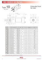
Extended front tie rods Unless otherwise specified, all dimensions are given in millimetres. Hydraulic and pneumatic cylinders
Open the catalog to page 15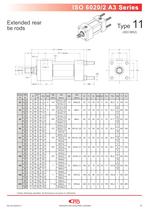
ISO 6020/2 A3 Series Extended rear tie rods Unless otherwise specified, all dimensions are given in millimetres. Hydraulic and pneumatic cylinders
Open the catalog to page 16
Tie rods extended on both ends Unless otherwise specified, all dimensions are given in millimetres. Hydraulic and pneumatic cylinders
Open the catalog to page 17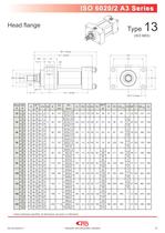
ISO 6020/2 A3 Series Head flange Unless otherwise specified, all dimensions are given in millimetres. Hydraulic and pneumatic cylinders
Open the catalog to page 18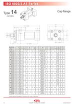
Unless otherwise specified, all dimensions are given in millimetres. Hydraulic and pneumatic cylinders
Open the catalog to page 19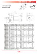
ISO 6020/2 A3 Series Front screwed tapped holes Unless otherwise specified, all dimensions are given in millimetres. Hydraulic and pneumatic cylinders
Open the catalog to page 20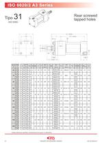
Rear screwed tapped holes Unless otherwise specified, all dimensions are given in millimetres. Hydraulic and pneumatic cylinders
Open the catalog to page 21
ISO 6020/2 A3 Series Double rod basic version Unless otherwise specified, all dimensions are given in millimetres. Hydraulic and pneumatic cylinders
Open the catalog to page 22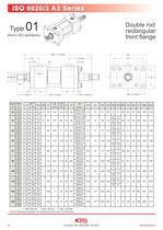
Double rod rectangular front flange * Max 200 bar ** Max 150 bar *** Max 120 Bar Unless otherwise specified, all dimensions are given in millimetres. Hydraulic and pneumatic cylinders
Open the catalog to page 23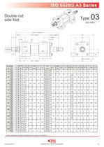
ISO 6020/2 A3 Series Double rod side foot Unless otherwise specified, all dimensions are given in millimetres. Hydraulic and pneumatic cylinders
Open the catalog to page 24
Double rod head trunnion Unless otherwise specified, all dimensions are given in millimetres. Hydraulic and pneumatic cylinders
Open the catalog to page 25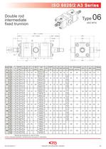
ISO 6020/2 A3 Series Double rod intermediate fixed trunnion * Specify the dimension in case of order. Unless otherwise specified, all dimensions are given in millimetres. Hydraulic and pneumatic cylinders
Open the catalog to page 26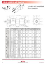
Double rod extended front tie rods Unless otherwise specified, all dimensions are given in millimetres. Hydraulic and pneumatic cylinders
Open the catalog to page 27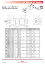
ISO 6020/2 A3 Series Double rod extended on both ends tie rods Unless otherwise specified, all dimensions are given in millimetres. Hydraulic and pneumatic cylinders
Open the catalog to page 28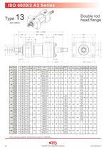
Double rod head flange Unless otherwise specified, all dimensions are given in millimetres. Hydraulic and pneumatic cylinders
Open the catalog to page 29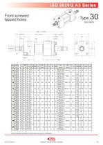
ISO 6020/2 A3 Series Front screwed tapped holes Unless otherwise specified, all dimensions are given in millimetres. Hydraulic and pneumatic cylinders
Open the catalog to page 30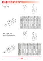
All dimensions are given in millimetres. T Rod eye with spherical bearing All dimensions are given in millimetres. Hydraulic and pneumatic cylinders
Open the catalog to page 31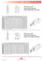
Rod eye with spherical bearing (ISO 6982/DIN 24338) All dimensions are given in millimetres. Rod eye with spherical bearing (ISO 8133/DIN 24555) All dimensions are given in millimetres. Hydraulic and pneumatic cylinders
Open the catalog to page 32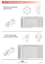
All dimensions are given in millimetres. Fork joint hinge with pin (ISO 8133) All dimensions are given in millimetres. Hydraulic and pneumatic cylinders
Open the catalog to page 33


