


CM6200 CIRCULAR MILLING MACHINE

CM6200 CIRCULAR MILLING MACHINE
This section provides an overview of the CM6200 Circular Milling Machine operating manual, including usage instructions, safety alerts, general and machine-specific safety precautions, risk assessment, and hazard mitigation. It also includes a checklist for risk assessment and label identification.
The overview section details the features and options of the CM6200, including machine components, operating dimensions, and specifications such as weight and hydraulic motor specifications.
This section covers the receipt and inspection of the machine, preparation for use, lifting and rigging, installation hazards, and the process of installing the machine on a workpiece. It includes detailed instructions for ID and OD mount leg assembly, mounting the machining arm, and positioning the counterweight.
The operation section provides guidance on operation setup, including pre-start checks, tool setup, and spindle tramming. It explains the use of the control pendant, coordinate systems, machine controls, and various movement options. It also covers circular milling, grinding options, and single-point options.
The manual specifies the sound power and pressure levels according to EN 3744 & EN 11201 standards, with declared levels for operators and bystanders.
CLIMAX offers a limited warranty for defects in materials and workmanship for one year on new machines and 90 to 180 days on parts and labor. The warranty excludes damage from improper maintenance, unauthorized modifications, or machine abuse. Terms of sale are also outlined.
Contact details for CLIMAX headquarters and regional offices are provided for customer support and service inquiries.
This manual provides essential information for the setup, operation, maintenance, storage, shipping, and decommissioning of the CM6200. Each chapter begins with a summary to help locate specific information, and appendices offer additional product details.
Safety alerts are crucial for identifying hazardous situations. They are categorized as DANGER, WARNING, CAUTION, and NOTICE, each indicating varying levels of risk.
Users must be aware of their work environment and follow safety guidelines, including receiving training, conducting risk assessments, using the machine as intended, wearing protective equipment, and maintaining a clear work area.
Additional precautions specific to the CM6200 include wearing eye and hearing protection, avoiding hazardous environments, securing loose clothing, and inspecting hoses and cables for damage.
Operators must understand the design intent and perform a risk assessment for each application. Checklists are provided to ensure all risks are mitigated.
Essential items not supplied with the machine include a torque wrench, level, dial indicator, support blocks, and scab plates.
The CM6200 machine offers several key features for optimal performance, including a kingpin clearance, a rigid rotational drive system, adjustable arms, a tubular rigid chucking system, a modular design, and touch screen controls.
The CM6200 is highly configurable with options such as ID and OD mounting, face mounting, single-point machining, and a grinding attachment.
Table 2-1 provides the maximum rotary speeds for different hydraulic motors during single-point machining.
The document details the components of the ID and OD mount setups, including the machining arm, counterweight assembly, adjustable chuck assembly, and more.
Figures outline the dimensions for ID and OD mount configurations, specifying minimum and maximum clearances, diameters, and heights.
Weight specifications for subassemblies are provided, along with hydraulic motor specifications.
This section covers the setup process, including receipt and inspection, pre-setup checks, work area assessment, and lifting and rigging procedures.
Warnings are provided regarding the risks associated with installation, such as swinging or falling machinery.
The document outlines the steps for installing the machine on a workpiece, including ID and OD mounting.
This section provides a detailed guide on setting up the CM6200 circular milling machine in the ID mounting configuration.
Key steps include ensuring power sources are disconnected, measuring the surface for mounting, and selecting appropriate parts for machining.
The ID mount leg assembly involves using leveling chuck feet jaws for internal flanges up to 8".
For OD mounting, the necessary length of the OD mount leg sections is determined based on the workpiece's outer diameter.
The machining arm is mounted on the rotary table using clamps.
The machining arm can be adjusted incrementally for versatile positioning.
The milling head mounts to the CM6200 using an adapter plate.
The counterweight must be installed for vertical machining applications to ensure stability and balance.
The counterweight in the machine serves to enhance performance by reducing the load on the servo drive motor.
Horizontal, vertical, and inverted mounting procedures are detailed.
To ensure precision, the machine must be centered and leveled using a dial indicator.
The machine is secured by torquing jacking screws and using additional securing methods.
Before connecting power cables, ensure the machine is secured to the workpiece.
Only trained operators should set up and operate the CM6200 machine.
Ensure the machine is turned off and locked out before performing checks.
Adjust the milling head using tramming screws to ensure proper alignment before machining.
Orient the spindle perpendicular to the machine tool, not the workpiece.
The machine uses absolute and incremental coordinate systems for positioning.
Provides access to all main screens for machine operation.
The Machine Setup Screen allows operators to adjust machine parameters.
The Incremental Move Screen controls operations based on a relative coordinate system.
Incremental and Absolute Velocity Move Screens control movement based on a percentage of maximum speed.
The Status Screen is used for troubleshooting.
Before machining, ensure the setup area is clear to prevent accidents.
To replace the milling assembly, de-energize the machine, remove the existing assembly, and attach the new tool head assembly.
Set the spindle over the workpiece, adjust speeds, and ensure the cutter is properly engaged before starting the rotary table.
The grinding attachment setup involves mounting the grinding head and adjusting screws for the desired angle.
Begin by turning on the grinding head and setting it to the desired speed.
This option requires an adapter and tool head assembly, along with pneumatic systems for feed control.
For ID or OD mount configurations, the rotary union is bolted to the CM6200 turntable plate or chuck inner diameter.
To replace the milling assembly with a single-point tool head, de-energize the power source, remove the milling head, and attach the single-point tool head assembly.
Set up the hydraulic drive by removing the servo motor and gearbox, installing the hydraulic motor, and connecting hoses.
Install the feed box adapter assembly onto the turning arm and mount the pneumatic feed box assembly.
Connect energy sources, adjust the turntable RPM, and set the feed rate.
Ensure the machine is properly rigged before disassembly.
Regular maintenance tasks include checking the pneumatic conditioning unit, maintaining the rotary table, and replacing the PLC battery.
Proper maintenance is crucial to avoid machine damage and warranty voidance.
Key tasks include checking for metal chips and rinsing parts exposed to salt water.
Use only approved lubricants to prevent damage and maintain warranty.
This section provides solutions for common issues such as machine not turning, feeding problems, poor cutting, and unexpected stops.
- Machining Arm Assembly: Includes detailed diagrams and parts lists for the machining arm.
- Milling Head Tram Assembly: Provides parts lists for the milling head tram assembly.
- Counterweight Arm Assembly: Details the components of the counterweight arm.
- Face Mount Assembly: Lists parts for the face mount assembly.
- Grinding Attachment Assembly: Describes the components for the grinding attachment.
- Grinder with Gear Reducer Assembly: Details the parts for a grinder assembly with a gear reducer.
- Single Point EU Assembly: Provides a comprehensive parts list for the single point EU assembly.
- Rotary Union Assembly: Lists components for the rotary union assembly.
- Specifications: Each assembly includes specific part numbers, dimensions, and quantities required for assembly.
- Safety Labels: Numerous safety labels are included throughout the document.
- Assembly Instructions: Detailed diagrams accompany each parts list.
Catalog excerpts
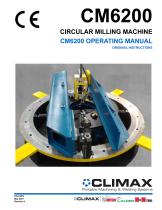
CM6200 CIRCULAR MILLING MACHINE CM6200 OPERATING MANUAL ORIGINAL INSTRUCTIONS
Open the catalog to page 1
©2021 CLIMAX or its subsidiaries. All rights reserved. Except as expressly provided herein, no part of this manual may be reproduced, copied, transmitted, disseminated, downloaded, or stored in any storage medium, without the express prior written consent of CLIMAX. CLIMAX hereby grants permission to download a single copy of this manual and of any revision hereto onto an electronic storage medium to be viewed and to print one copy of this manual or any revision hereto, provided that such electronic or printed copy of this manual or revision must contain the complete text of this copyright notice...
Open the catalog to page 3
CLIMAX GLOBAL LOCATIONS
Open the catalog to page 4
The Declared Operator Sound Pressure Level is: The Declared Bystander Sound Pressure Level is: The Declared Sound Power Level is:
Open the catalog to page 6
LIMITED WARRANTY Climax Portable Machine Tools, Inc (hereafter referred to as “CLIMAX”) warrants that all new machines are free from defects in materials and workmanship This warranty is available to the original purchaser for a period of one year after delivery If the original purchaser finds any defect in materials or workmanship within the warranty period, the original purchaser should contact its factory representative and return the entire machine, shipping prepaid, to the factory CLIMAX will, at its option, either repair or replace the defective machine at no charge and will return the...
Open the catalog to page 7
This page intentionally left blank
Open the catalog to page 8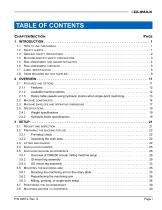
TABLE OF CONTENTS CHAPTER/SECTION HOW TO USE THIS MANUAL . . . . . . . . . . . . . . . . . . . . . . . . . . . . . . . . . . . . . . . . . . . . . . . . . . . . . . . . . . SAFETY ALERTS . . . . . . . . . . . . . . . . . . . . . . . . . . . . . . . . . . . . . . . . . . . . . . . . . . . . . . . . . . . . . . . . . . GENERAL SAFETY PRECAUTIONS . . . . . . . . . . . . . . . . . . . . . . . . . . . . . . . . . . . . . . . . . . . . . . . . . . . . . . MACHINE-SPECIFIC SAFETY PRECAUTIONS . . . . . . . . . . . . . . . . . . . . . . . . . . . . . . . . . . . . . . . . . . . . . . . RISK ASSESSMENT...
Open the catalog to page 9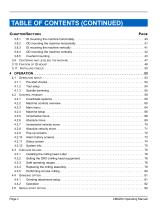
TABLE OF CONTENTS (CONTINUED) CHAPTER/SECTION 3.8.1 ID mounting the machine horizontally . . . . . . . . . . . . . . . . . . . . . . . . . . . . . . . . . . . . . . . . . . . 3.8.2 OD mounting the machine horizontally . . . . . . . . . . . . . . . . . . . . . . . . . . . . . . . . . . . . . . . . . . 3.8.3 ID mounting the machine vertically . . . . . . . . . . . . . . . . . . . . . . . . . . . . . . . . . . . . . . . . . . . . . 3.8.4 OD mounting the machine vertically . . . . . . . . . . . . . . . . . . . . . . . . . . . . . . . . . . . . . . . . . . . . 3.8.5 Inverted mounting . . . . . . ....
Open the catalog to page 10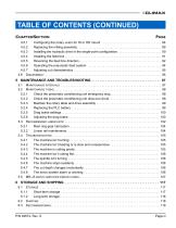
TABLE OF CONTENTS (CONTINUED) CHAPTER/SECTION 4.5.1 Configuring the rotary union for ID or OD mount . . . . . . . . . . . . . . . . . . . . . . . . . . . . . . . . . 4.5.2 Replacing the milling assembly. . . . . . . . . . . . . . . . . . . . . . . . . . . . . . . . . . . . . . . . . . . . . . . . 4.5.3 Installing the hydraulic drive in the single-point configuration . . . . . . . . . . . . . . . . . . . . . . . . . 4.5.4 Installing the feed box . . . . . . . . . . . . . . . . . . . . . . . . . . . . . . . . . . . . . . . . . . . . . . . . . . . . . . . 4.5.5 Reversing the feed box direction....
Open the catalog to page 11
TABLE OF CONTENTS (CONTINUED) CHAPTER/SECTION MR-J4 SERVO AMPLIFIER MANUAL . . . . . . . . . . . . . . . . . . . . . . . . . . . . . . . 179
Open the catalog to page 12
LIST OF FIGURES FIGURE 2-1 ID mount components . . . . . . . . . . . . . . . . . . . . . . . . . . . . . . . . . . . . . . . . . . . . . . . . . . . . . . . . . . . . . .14 2-2 Rotation direction for hydraulic motor, rotation table, and milling head . . . . . . . . . . . . . . . . . . . . . . . . .15 2-3 OD mount components . . . . . . . . . . . . . . . . . . . . . . . . . . . . . . . . . . . . . . . . . . . . . . . . . . . . . . . . . . . . . .16 2-4 ID mount machine dimensions . . . . . . . . . . . . . . . . . . . . . . . . . . . . . . . . . . . . . . . . . . . . . . . . . . . . . . . .17 2-5...
Open the catalog to page 13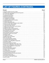
LIST OF FIGURES (CONTINUED) FIGURE 4-4 Spindle rotated to the ram surface . . . . . . . . . . . . . . . . . . . . . . . . . . . . . . . . . . . . . . . . . . . . . . . . . . . . 4-5 Milling head mounting plate and tramming points . . . . . . . . . . . . . . . . . . . . . . . . . . . . . . . . . . . . . . . . . 4-6 Y-axis screw adjustment . . . . . . . . . . . . . . . . . . . . . . . . . . . . . . . . . . . . . . . . . . . . . . . . . . . . . . . . . . . . 4-7 X-axis screw location. . . . . . . . . . . . . . . . . . . . . . . . . . . . . . . . . . . . . . . . . . . . . . . . . . . . . . . . ....
Open the catalog to page 14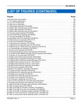
LIST OF FIGURES (CONTINUED) FIGURE 4-49 Hose tower stow position. . . . . . . . . . . . . . . . . . . . . . . . . . . . . . . . . . . . . . . . . . . . . . . . . . . . . . . . . . . 96 5-1 PLC battery specification. . . . . . . . . . . . . . . . . . . . . . . . . . . . . . . . . . . . . . . . . . . . . . . . . . . . . . . . . . . . 99 5-2 Top view of drag brake . . . . . . . . . . . . . . . . . . . . . . . . . . . . . . . . . . . . . . . . . . . . . . . . . . . . . . . . . . . . 100 5-3 Side view of drag brake . . . . . . . . . . . . . . . . . . . . . . . . . . . . . . . . . . . . . . . . . ....
Open the catalog to page 15
LIST OF FIGURES (CONTINUED) FIGURE Page viii
Open the catalog to page 16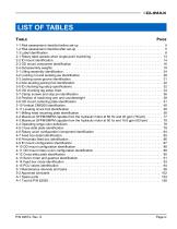
LIST OF TABLES TABLE 1-1 Risk assessment checklist before set-up . . . . . . . . . . . . . . . . . . . . . . . . . . . . . . . . . . . . . . . . . . . . . . . . 5 1-2 Risk assessment checklist after set-up . . . . . . . . . . . . . . . . . . . . . . . . . . . . . . . . . . . . . . . . . . . . . . . . . . 5 1-3 Label identification . . . . . . . . . . . . . . . . . . . . . . . . . . . . . . . . . . . . . . . . . . . . . . . . . . . . . . . . . . . . . . . . . 6 2-1 Rotary table speeds when single-point machining . . . . . . . . . . . . . . . . . . . . . . . . . . . . . . . . . . . . . . . . 13...
Open the catalog to page 17
This page intentionally left blank
Open the catalog to page 18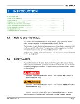
IN THIS CHAPTER: 1.1 HOW TO USE THIS MANUAL - - - - - - - 1.2 SAFETY ALERTS - - - - - - - - - - - - 1.3 GENERAL SAFETY PRECAUTIONS - - - - 1.4 MACHINE-SPECIFIC SAFETY PRECAUTIONS 1.5 RISK ASSESSMENT AND HAZARD MITIGATION 1.6 RISK ASSESSMENT CHECKLIST - - - - - 1.7 LABEL IDENTIFICATION - - - - - - - - - 1.8 ITEMS REQUIRED BUT NOT SUPPLIED - - - - HOW TO USE THIS MANUAL This manual describes information necessary for the setup, operation, maintenance, storage, shipping, and decommissioning of the CM6200. The first page of each chapter includes a summary of the chapter contents to help you locate...
Open the catalog to page 19All CLIMAX catalogs and technical brochures
 BB7100 LINE BORING MACHINE
8 Pages
 PL2000 PORTABLE LATHE
6 Pages
 BW1000 WELDING MACHINE
50 Pages
 BB3000 LINE BORING MACHINE
8 Pages
Archived catalogs
 Flange Facing
4 Pages
- Turning center
- Grinding machine
- Grinding mill
- Drill
- Pack unit
- Vertical pulverizer
- Automatic grinding machine
- 3-axis milling machine
- Vertical milling machine
- Pneumatic drill
- Powerful turning machine
- Compact turning machine
- Precision turning machine
- Vertical grinding machine
- Large part turning machine
- Compact drill
- Robust grinding mill
- Compact grinding machine
- High-performance mill