

31188
31188
This manual offers detailed guidance on the setup, operation, maintenance, troubleshooting, and replacement parts for Pro-Series Big Clem Bulk Blast Machines, emphasizing safety and understanding before use.
The manual covers various aspects of the blast machines, including accessory manuals, stressing the need for trained operators aware of safety practices.
Safety alerts follow ANSI standards, indicating hazard levels from 'Notice' to 'Danger', crucial for preventing injuries or fatalities.
The machines come in three sizes and models, each with specific components like pressurization valves and remote controls, certified to ASME standards.
Instructions for setting up and operating the machines include pressurizing the abrasive chamber, loading abrasives, and starting the blasting process, with a focus on safety equipment and procedures.
Guidelines for adjusting abrasive flow and performing preventive maintenance are included, with regular inspections recommended for safe operation.
Instructions for addressing common issues like blockages and replacing parts are provided, emphasizing proper handling and servicing of components.
Solutions for common problems with pneumatic and electric remote controls are offered to ensure efficient operation.
A list of available accessories and replacement parts is provided, with instructions for installation and use.
The system ensures safety by stopping blasting when the operator releases the control handle lever, using normally closed valves that open when pressed and close when released.
Blast Machine: Pressurizes the abrasive chamber using hand-operated valves. Blasting starts when the remote control lever is pressed.
Pneumatic Remote Controls: Recommended for distances within 100 feet, operating on a return-air principle.
Electric Remote Controls: Suitable for distances over 100 feet and in cold weather, using electric circuits to control pneumatic operations.
The ACS allows the operator to close the abrasive valve independently, clearing abrasive from the hose.
Air requirements depend on nozzle size and the number of operating stations, with tables providing approximate air consumption.
Using the correct abrasive is crucial for safety and machine maintenance, with guidelines provided for selecting appropriate abrasives.
Portable machines have specific GVWR limits, with tare weights and maximum GVWR provided for different models.
Yard and highway towable models differ in braking systems and safety equipment, with proper installation of an electric-brake controller necessary.
Ensure the hitch is approved based on GVWR and adjust its height to match the trailer when empty and level.
The safety chain requires an approved fastening device, and the breakaway chain should be attached to the tow vehicle with enough slack.
Attach air-supply hose fittings to the compressed-air inlet ports, with compressor size and air hose requirements depending on nozzle size.
Ensure control lines and blast hoses are correctly connected and marked to prevent accidental actuation.
Color-code each operator station and blast hose assembly to prevent accidental hose switching.
Ensure all connections are made correctly to prevent unintended actuation of blast lines.
Ensure all fittings are tight to prevent leaks, with operator stations color-coded for easy identification.
Install the GW Electric RLX Control Handle to the blast hose, ensuring the blast hose and control cord are of equal length and banded together.
Use colored straps to color-code each set, maintaining separate controls for each operator.
Depressurize the abrasive chamber and disconnect all hoses and control lines before towing.
Load abrasive only after initial tests are completed, ensuring all safety measures are in place.
Ensure the compressor reaches operating temperature and pressure, maintaining pressure above 80 psi.
To pressurize, close the exhaust valve and open the pressurization valve. Reverse the process to depressurize.
Test the machine with air only before loading abrasive, ensuring control handles function correctly.
Unlock the fill-port cover for loading and secure it to prevent moisture and debris entry.
Attach rack guides and use lifting equipment to position the rack for loading abrasive.
Depressurize the chamber before loading, ensuring abrasives do not exceed the machine's weight capacity.
Operators must wear NIOSH-approved respirators, protective clothing, and hearing protection.
Ensure all safety measures are in place, including closing safety valves on active stations.
Safety valves prevent accidental operation, ensuring they are open when not blasting.
The ACS allows air-only operation to clear hoses or blow off surfaces.
Keep the choke valve open during blasting, temporarily closing it to clear minor blockages.
Use the ACS switch to shut off abrasive flow before releasing the control handle.
In humid conditions, empty the chamber to prevent condensation.
Empty the abrasive chamber, open safety valves, depressurize the chamber, and shut down the compressor.
Adjust the flow by turning the knob, using experience to determine the optimal flow.
Use only when temperatures fall below freezing, adjusting the flow rate to prevent system freezing.
Establish a daily inspection schedule, inspecting all parts in contact with abrasive.
Inspect hoses for soft spots and replace as needed, checking nozzle and holder threads for wear.
Regularly inspect the remote control system and clean around control handles.
Separate manuals are provided for specific components, with detailed service instructions.
For minor blockages, rapidly close and open the choke valve several times.
If moisture causes damp abrasive, consider using an aftercooler or air dryer.
Use caution to avoid injury from the cover's weight, inspecting and replacing the cover gasket if worn.
Empty the abrasive chamber and remove the manway cover, using a pipe wrench to unscrew the pop-up guide.
Control hoses can be shortened and cut to length, ensuring not to over-tighten the sleeve.
Follow specific wire and pole coding when replacing electrical connectors.
Ensure all safety measures are in place before troubleshooting, with common issues including pop-up valve not sealing and irregular abrasive flow.
- Blasting does not stop when control handle lever is released: Inspect the pneumatic adaptor gasket and exhaust port.
- Air or abrasive leaks from nozzle: Service the ACE Air Valve or check for blockages.
- Heavy abrasive flow: Ensure the choke valve is open and adjust the abrasive metering valve.
- Air flow only - no abrasive: Ensure the machine contains abrasive and the ACS is in the ON position.
- Abrasive flow continues after control handle lever is released: Check for full exhaustion of control air.
- Troubleshooting electric remote controls: Ensure the abrasive chamber is pressurized and safety valves are closed.
- Blasting does not stop with electric controls: Remove the exhaust muffler to check for blockages.
- Air or abrasive leaks with electric controls: Close the choke valve to identify the leaking valve.
- Heavy abrasive flow with electric controls: Ensure the choke valve is open and adjust the abrasive metering valve.
- Air flow only - no abrasive with electric controls: Ensure the machine contains abrasive and the ACS switch is pressed.
- Abrasive flow continues after control handle lever is released with electric controls: Check for electrical shorts.
- Check the RLX Control Handle, control panel, and control cords.
- Remove the exhaust muffler from the control panel if flow stops.
- Ensure the air-assist vent valve is closed and the metering valve’s safety valve is open.
- Check the operation of the 4-way valve.
- If abrasive flow continues after the ACS button is off, check the exhaust port and exhaust filter.
- Inspect the RLX Control Handle, control panel, and control cords for faults.
- With the control handle in the nonblast position, gradually open the air-assist vent valve.
- Press and release the control handle lever to check for air bursts from the exhaust mufflers.
- Replace the 4-way valve if it does not operate correctly.
- Refer to Section 1.1.1 for replacement parts for accessories.
- Various parts and their stock numbers are listed for maintenance and replacement.
- Figures 35 to 40 provide visual guidance for the operation and parts of the blast machines and control panels.
- Each figure includes detailed descriptions and stock numbers for components.
Catalog excerpts

© 2022 CLEMCO INDUSTRIES CORP. One Cable Car Dr. Washington, MO 63090 Phone (636) 239-4300 Fax (800) 726-7559 Email: [email protected] www.clemcoindustries.com PRO-SERIES BIG CLEM BULK BLAST MACHINES O. M. 31188 DATE OF ISSUE: 08/22 REVISION: Do not use this equipment before READING this MANUAL and UNDERSTANDING its contents. These WARNINGS are included for the health and safety of the operator and those in the immediate vicinity. Failure to read and understand these warnings can result in injury or death. Electronic files include a preface containing the same important information as in the orange cover.
Open the catalog to page 1
PRO-SERIES BIG CLEM BULK BLAST MACHINES 1.0 Safety Alerts 1.2.1 Clemco uses safety alert signal words, based on ANSI Z535.4-2011, to alert the user of a potentially hazardous situation that may be encountered while operating this equipment. ANSI's definitions of the signal words are as follows: This is the safety alert symbol. It is used to alert you to potential physical injury hazards. Obey all safety messages that follow this symbol to avoid possible injury or death. Notice indicates information that is considered important, but not hazard-related, if not avoided, can result in property...
Open the catalog to page 2
PRO-SERIES BIG CLEM BULK BLAST MACHINES Basic components 1.4.1.1 Key components for Pro-Series Big Clem Bulk Blast Machines are shown in Figure 1. Bulk blast machines come in three sizes: 60, 120 and 160-cuft capacity. Each size is available in a stationary, yardtowable, and highway-towable models. Highway towable models include fenders, lights and electric brakes. Pneumatic remote controls are shown in Figure 2, and electric remote controls are shown in Figure 3. 1.4.1.2 Pro-Series Big Clem blast machines are furnished with manually operated pressurization and exhaust (bleed-off) valves, 1-1/2"...
Open the catalog to page 3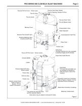
PRO-SERIES BIG CLEM BULK BLAST MACHINES Pop-Up-Valve Seat, Rubber Pop-Up Fill-Port Cover – Shown open. Pop-Up Opening, Abrasive Fill Port Pop-Up Valve Pop-Up Guide Pop-Up Check Valve Pop-Up Bypass Valve Manway Cover Pressurization Valve Water Separator Abrasive-Flow Shutoff Valve Compressed-Air Inlet Ports Abrasive Metering Valve Includes shutoff valve. 5 1 3 Water Drain Pusher Lines Lifting Eyes Lift empty machine only. Use a spreader to distribute weight and lift vertically. Pop-up Fill-Port Cover – Shown closed. Super-Sack Guide Mounts Exhaust Muffler Hose Rack The hose rack and ladder can...
Open the catalog to page 4
PRO-SERIES BIG CLEM BULK BLAST MACHINES Welding, grinding, or drilling on the abrasive chamber or water separator can weaken the vessel. Compressed-air pressure can cause a weakened blast machine to rupture, resulting in death or serious injury. Welding, grinding, or drilling on the vessels without a National Board R stamp voids the Clemco ASME certification. 1.4.2.2 All welding repairs to the vessel must be performed by certified welders at shops holding a National Board R Stamp. Welding performed by any welder not properly qualified per the ASME code voids the Clemco ASME certification. 1.4.2.3...
Open the catalog to page 5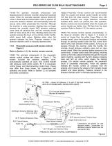
PRO-SERIES BIG CLEM BULK BLAST MACHINES 1.5.1.2 The operator manually pressurizes and depressurizes the abrasive chamber using hand-operated valves. When the manually operated exhaust (bleed-off) valve is closed and the pressurization valve is opened, air enters the abrasive chamber and automatically seals the pop-up valve, which pressurizes the chamber. Although the machine is under pressure, blasting does not begin because the normally closed (NC) abrasive metering valve shuts off abrasive flow, and the normally closed ACE Air Valve shuts off air flow. Blasting starts when the operator presses...
Open the catalog to page 6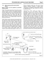
PRO-SERIES BIG CLEM BULK BLAST MACHINES 1.5.3 Electric pressure-hold remote controls Figure 3 Refer to Section 1.5.2 for operation of pneumatic remote controls. 1.5.3.1 The principal components of the electric remote control are shown in Figure 3, The systems include the abrasive metering valve, ACE Pneumatically-Operated Air Valve, GW Electric RLX Control Handle with abrasive cutoff (ACS) switch, 50 ft electric control cord, and interconnecting control lines. Valves may differ from those shown, but connections and operation are similar. Refer to Section 2.5 to complete electric controls and...
Open the catalog to page 7
PRO-SERIES BIG CLEM BULK BLAST MACHINES 1.5.4 Abrasive cutoff switch (ACS) 1.5.4.1 An abrasive cutoff switch (ACS) is a standard feature of the pressure-hold remote controls. The operator uses the switch to close the abrasive valve independently of the air valve so that air without abrasive exits the nozzle. This feature is used to clear abrasive from the blast hose and to blowdown the blasted surface. • Pneumatic ACS: The ACS switch is mounted on the RLX Control Handle, as shown in Figure 2. • Electric ACS: The ACS switch is wired into the box at the back of the RLX handle, as shown in Figure...
Open the catalog to page 8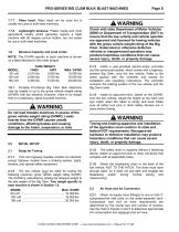
PRO-SERIES BIG CLEM BULK BLAST MACHINES MODEL 60 cuft 120 cuft 160 cuft 1.7.7 Glass bead: Glass bead can be used but is usually not used in bulk blast machines. 1.7.8 Lightweight abrasive: Plastic media and most agricultural media, which generally require a blast machine with 60 degree conical bottom, are not suited for use in bulk blast machines. 1.8 Abrasive Capacity and Load Limits NOTE: The GVWR specific to each machine is shown on a label attached to the trailer tongue. TARE WEIGHT YARD HWY 1.8.1 Portable Pro-Series Big Clem Bulk Machines may be loaded to up to the gross vehicle weight rating...
Open the catalog to page 9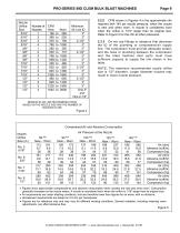
MINIMUM ID AIR LINE RECOMMENDATIONS BASED ON THE NOZZLE SIZE AND THE NUMBER OF NOZZLES IN USE 2.2.2 CFM shown in Figures 4 is the approximate cfm required with 140 psi nozzle pressure, when the nozzle is new and when worn. A nozzle is considered worn when the orifice is 1/16" larger than its original size. Refer to Figure 5 for the cfm at other pressures. 2.2.3 Do not use fittings or adaptors that decrease the ID of the plumbing or compressed-air supply line. The compressor must provide adequate output, and the hose or plumbing between the compressor and the blast machine inlet ports must have...
Open the catalog to page 10All CLEMCO INDUSTRIES catalogs and technical brochures
Archived catalogs
 Cool Air Tube (Rev. B)
2 Pages
 CALIPSO Ambient Air Pump
2 Pages
 Bulk Abrasive Blast Machines
2 Pages
 Blast Suit & Gloves (Rev. E)
2 Pages
 Pre-assembled blast-room
4 Pages
 Super Comet
4 Pages
 INEX Blast Cabinet (Rev. E)
2 Pages
 CDF Dust Collectors (Rev. C)
4 Pages
 MB series
2 Pages
 BNP Suction Blast Guns
2 Pages
 Tumble Cabinets
2 Pages
 CAP-4 Ambient Air Pump
2 Pages
 Big Clem Bulk Blast Machines
2 Pages
 Internal Pipe Tools (Rev. A)
8 Pages
 Blast Suit & Gloves (Rev. I)
2 Pages
 RPH
RPH11 Pages
 RPC-2
RPC-212 Pages
 COMFORT VEST
7 Pages
 FLAT-TRAK ®
29 Pages
 Clemco Mule
1 Page
 Pulsar III-P
2 Pages
 Operator Safety Equipment
8 Pages
 Pulsar IX Pressure PS
2 Pages
 Pulsar III-PE
2 Pages
 Pulsar III, VI & VI-P
6 Pages
 Pulsar VI-PE
2 Pages
 ZERO Automation
8 Pages
 Climate Control Tube (CCT)
2 Pages
 Apollo 60 and 600
4 Pages
 Options Plus
4 Pages
 Cabinet Dust Collectors
8 Pages
 Automated Air Blast Systems
8 Pages
 BNP A200 Series
4 Pages
 Debris Screen Basket
1 Page
 Tumble Cabinets
8 Pages
 CLASSIC SERIES
12 Pages
 Wetblast FLEX
2 Pages
 Apollo 20 HP
2 Pages
 Apollo 600
4 Pages
 Automated Air Blast Systems
6 Pages


- Manual valve
- Filter with cartridge
- Gas detector
- Dust collector
- Monitoring detector
- Miniature valve
- Flow controller
- Filter dust collector
- In-line filter
- Compressed air pre-filter
- Pneumatic flow regulator
- Detector with alarm
- Carbon monoxide detector
- Blast room
- Compact detector
- Sandblasting machine
- Recuperator
- Manual blast room