【NEW】ABP2-HP1 Series Specifications・How to order・Dimensions
1 /7Pages

【NEW】ABP2-HP1 Series Specifications・How to order・Dimensions
1 /7Pages
Catalog excerpts
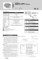
Working fluid From a primary pressure of +0.1MPa to twice the primary pressure (max. 0.99MPa) Proof pressure Body port thread B ressure P gauge option Flow rate m3 /min(ANR) Refer to the flow characteristics in the graph on the right Boosting ratio Ambient temp Port size Weightkg Durability A Body port thread: Rc thread C Silencer option: Silencer (2 pcs. included) D Bracket option: None Rc thread NPT thread (made to order) G thread (made to order) No Pressure gauge (2 included) No Silencer (2 pcs. included) High performance silencer (2 pcs. included) Functions Internal air circuit diagram No Foot bracket (2 included) Base for mounting tank Pressure adjustment section Switching valve Booster chamber B IN side check valve P rimary pressure from IN passes through the check valve on IN side, and flows into booster chambers A and B.The primary pressure passes through the pressure adjustment section and switching valve, and flows into the driving chamber A. The piston moves to the left due to the pressure of the driving chamber A. Air in booster chamber A is compressed, passes through the check valve on the OUT side, and goes to the OUT side. W hen the piston reaches the stroke end, the changeover switch will be pushed, causing compressed air to be supplied to the switching valve pilot chamber and causing the switching valve to change over. Then the air in drive chamber A is exhausted, and the air is delivered to drive chamber B. T herefore, the piston moves to the right and air in booster chamber B is compressed, passes through the check valve at the OUT side and moves OUT. I f the above operations are repeated, pressure will be increased on the OUT side. Feedback pressure is transmitted to the pressure adjustment section due to the OUT side pressure, and boosting is continued until the pressure adjustment spring pressure is balanced. Silencer option Silencer option B Pressure gauge option: Pressure gauge (2 included) Bracket option Pressure gauge option 10 million cycles (nominal) (Refer to page 2) Selection switch Piston Body port thread Piston OUTside check valve Fixed orifice OUTside (Secondary pressure)
Open the catalog to page 1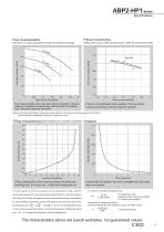
Flow characteristics (with the 5 L air tank, equivalent to double the pressure increase) Pressure characteristics (Setting: primary pressure: 0.7MPa, secondary pressure: 1.0MPa, flow rate: 0.02m3/min (ANR)) Fluid characteristics show max. flow rate of air booster. If primary pressure is constant and secondary side flow rate is increased, max. secondary pressure decreases. Pressure characteristics show variation of set secondary pressure according to primary pressure variation. Note) Air booster needs approx. twice secondary side flow rate (max.) for primary side due to structure. Confirm that...
Open the catalog to page 2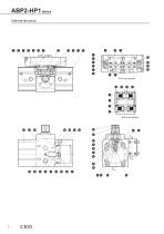
ABP2-HP1 Series Internal structure
Open the catalog to page 3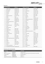
ABP2-HP1 Series Parts list Parts list Part No. Part name Part No. Part name Hexagon socket head cap screw Stainless steel Valve seat Aluminum alloy Spring washer Stainless steel Nitrile rubber Flat washer Stainless steel Cylinder body Aluminum alloy Stainless steel Aluminum alloy Nitrile rubber Side plate Aluminum alloy Nitrile rubber Nitrile rubber Detection valve body Aluminum alloy Nitrile rubber Wear ring Nitrile rubber Aluminum alloy Fixed orifice Stainless steel Hexagon socket set screw Stainless steel Stainless steel Stainless steel Hexagon socket set screw Stainless steel Oiles drymet...
Open the catalog to page 4
When mounting pressure gauge/silencer/bracket
Open the catalog to page 5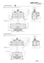
When mounting pressure gauge, high performance silencer, bracket Optional dimensions When mounted on the back of the bracket
Open the catalog to page 6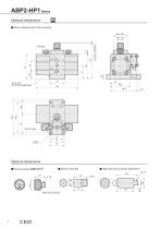
ABP2-HP1 Series Optional dimensions When installing base for tank mounting ø20, 49.6 High performance silencer (SLW-8A-H)
Open the catalog to page 7All CKD catalogs and technical brochures
 【NEW】ABP2-HP1・AT2 Series Catalog
16 Pages
 FP Series Precautions
7 Pages
 FP Series Introduction
10 Pages
 【NEW】WFK2 Series Catalog
24 Pages
 【NEW】WFK2 Series Precautions
6 Pages
 MN4GA / 4GB
140 Pages
 4GD1 to 3R, 4GE1 to 3R
261 Pages
 MV3QR
MV3QR16 Pages
 4F ** 0EX series
28 Pages
 Pilot operated 5-port valve
74 Pages
 MV3QRA1/MV3QRB1 Series
20 Pages
 PV5G/PV5/GMF/PV5S-0
76 Pages
 4G unit valve
4 Pages
 SCP*3 Series
60 Pages
 SCS2 series
56 Pages
 Rodless cylinder SRL3
89 Pages
 Linear slide cylinder LCG
58 Pages
 Linear slide cylinder LCM
52 Pages
 Linear slide cylinder LCX
64 Pages
 Guided cylinder STM
24 Pages
 Cartridge cylinder CAT
6 Pages
 Compact cylinder SSD
221 Pages
 Compact cylinder SSD2
278 Pages
 Guided compact cylinder SSG
16 Pages
 Medium bore size cylinder SCS
46 Pages
 Medium bore size cylinder SCA2
161 Pages
 Tie rod cylinder SCG
87 Pages
 Medium bore size cylinder CMK2
107 Pages
 Round shaped cylinder SCM
116 Pages
 Medium bore size cylinder CMA2
20 Pages
 Pencil shaped cylinder SCP*3
60 Pages
 LMD series
15 Pages
 KBZ series
64 Pages
 AGD21R-A series
4 Pages
 WXU series
32 Pages
 AX6000M
24 Pages
 SCS-G Series
2 Pages
 CMK2 SR
7 Pages
 CMK2 Series Double acting
7 Pages
 SSD-F/SSD-KF Series
1 Page
 CMK2-T Series
1 Page
 SCPS2-V Series
4 Pages
 SCPD2-*C Series
1 Page
 SCPD2-K Series
3 Pages
 SCPS2-MSeries
4 Pages
 SCPD2-D/SCPD2-DT Series
3 Pages
 SCPD2-F Series
2 Pages
 SCPD2 Serie
3 Pages
 SCPD2 Series
2 Pages
 SCPS Series
1 Page
 SCM Series ø 20 to ø 63
2 Pages
 SCM Series
2 Pages
 GHV series
4 Pages
 High purity gas systems
2 Pages
 Component for chemicals
2 Pages
 Labor-Saving products
8 Pages
 General purpose valve
1 Page
 Pneumatic valves
8 Pages
 Pneumatic cylinders
12 Pages


Archived catalogs


- Manual valve
- Control valve
- Flowmeter
- Pneumatic valve
- Volume flow monitor
- Actuator
- Electrically operated valve
- Regulating valve
- Linear actuator
- Electric actuator
- Packing machine
- Gas solenoid valve
- 2-way solenoid valve
- NC solenoid valve
- Directional control valve
- Gas valve
- Double-acting cylinder
- Direct-operated solenoid valve