Guided cylinder STM
1 /24Pages

Guided cylinder STM
1 /24Pages
Catalog excerpts

Super-Mini Complete with Easy-to-Use Functions Guided Cylinder GUIDED CYLINDER STM SERIES
Open the catalog to page 1
Super-Mini Complete with Super-mini Guided Cylinder STM Series (ø6, ø10) with free installation and wide variations to facilitate use and selection Product lineup including ball bearing and clean-room specifications High-performance guide The structure features an outstanding rod revolvable angle tolerance of ±0.08*, high rigidity, and tolerance against lateral loads. * For ball bearing type (STM-B) Super-mini Smallest model is just 33 mm wide and 15.5 mm high. This is the smallest space-saving guided cylinder available. Guided Cylinder
Open the catalog to page 2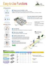
Piping direction Piping to rear and installed on side Piping is connected to the front or centrally led from the rear. (Option) Installation on the cylinder is possible, allowing several units to be installed in a small space. (Option) Two-color indicator switch installable Front piping The two-color indicator reed switch can be installed on all types. The switch's lead is led out horizontally or vertically. Front installation Rear piping (option) Installation direction Side installation (option) Rear piping (option) * All options are shown in the photo for explanatory purposes. On the actual...
Open the catalog to page 3
Series variation Guided Cylinder STM Series Stroke length (mm) Model no. Bore size Double acting single rod type ø10 STM-B-P7* Double acting single rod type Clean room specications ø10 Note 1: Consult with CKD for combinations of clean room specications and rear piping type.
Open the catalog to page 4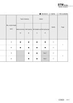
Series variation #: Standard ©: Option : Not available
Open the catalog to page 5
Safety precautions Always read this section before starting use. When designing and manufacturing a device using CKD products, the manufacturer is obligated to check that device safety mechanism, pneumatic control circuit, or water control circuit and the system operated by electrical control that controls the devices is secured. It is important to select, use, handle, and maintain the product appropriately to ensure that the CKD product is used safely. Observe warnings and precautions to ensure device safety. Check that device safety is ensured, and manufacture a safe device. WARNING 1 This...
Open the catalog to page 6
Pneumatic components Safety precautions Always read this section before starting use. Refer to Pneumatic Cylinders (CB-029SA) for details on general cylinders and cylinder switches. Precautions: Guided Cylinder STM Series Design & Selection 3. Clean room specications CAUTION When using the STM-B-6 with a two-color indicator reed switch, the cylinder cannot be installed on a magnetized device (steel plates, etc.). Installation will result in switch detection faults. Precautions for using relief ports Exhaust gas (P72) cannot be treated with vacuum sweeping. This also applies for the reverse application....
Open the catalog to page 7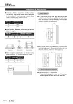
STM Series Installation & Adjustment A rubber cushion is assembled into the cylinder. The following table shows kinetic energy absorbed by the cushion. If kinetic energy exceeds these values, consider using another cushion. Bore size (mm) Allowable energy absorption (J) If a magnetized device (steel plate, etc.) is near the cylinder switch, the cylinder switch could malfunction. Keep all magnetic materials at least 20 mm from the cylinder. (Same for all bore sizes.) When installing with a bolt, tighten with the following tightening torque: Tightening torque (N m) Thread size Through bolt Side...
Open the catalog to page 8
M. Clean room specifications J ■ Fluoro grease is used in P7 series. Lighting a cigarette with fluorine-based grease on hands generates toxic
Open the catalog to page 9
Guided cylinder Double acting single rod type STM- M Series B Bore size: ø6, ø10 Specications Descriptions Bore size Port size Stroke tolerance Working piston speed mm/s Rubber cushioned Not required (when lubricating, use turbine oil Class 1 ISO VG32.) Allowable energy absorption J Stroke length Bore size Standard stroke length (mm) Max. stroke length (mm) Note: Other than standard stroke length is custom order. Min. stroke length of types with switch
Open the catalog to page 10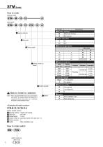
Without switch ©Bearing method ©Stroke length ©Switch quantity £± Note on model no. selection _ Note 1: When using the STM-B-6 with a two-color indicator ©Option reed switch, the cylinder cannot be installed on a magnetized device (steel plate, etc.). Installation will result in switch detection faults. <Example of model number> Model: Guided cylinder metal bush bearing proximity switch F2H, lead wire 1 m Side installation type
Open the catalog to page 12
Internal structure and parts list Internal structure and parts list Metal bush bearing Ball bearing *This product can not be disassembled. No. Parts name Aluminum alloy Stainless steel Nitrile rubber Aluminum alloy Aluminum alloy Urethane rubber Hexagon socket head set screw Stainless steel Stainless steel Hexagon socket head set screw Stainless steel Tube body Aluminum alloy Stainless steel Oil impregnated copper alloy Piston packing seal Urethane rubber Alloy steel Nitrile rubber Ball bearing Piston magnet Chromate Hard alumite Industrial chrome plating (ø10) Industrial chrome plating
Open the catalog to page 13
STM Series Dimensions A + stroke length B + stroke length Symbol Bore size (mm) Standard stroke length (mm) Symbol Bore size (mm) 6.1 spot face depth 3.3 8 spot face depth 4.4 Dimensions with options Side installation type (A) Symbol Bore size (mm) Standard stroke length (mm)
Open the catalog to page 14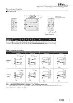
Dimensions with options, switch installating position Dimensions with options I Rear piping type (R) /(Head end pressure port) Note 1: The product is shipped in Installation A with the switch assembled. Note 2: If the switch is installed as shown in Installation B, it may protrude from the main device. If the switch protrudes from the cylinder and the product is installed on the head, the switch will interfere with the system. Note 3: Dimensions in ( ) apply to rear piping.
Open the catalog to page 15
Guided cylinder Double acting single rod type Clean room specications STM-B-P7* Series Bore size: ø6, ø10 Specications Descriptions Bore size Port size Relief port size Stroke tolerance Working piston speed mm/s Rubber cushioned Allowable energy absorption J Stroke length Bore size Standard stroke length (mm) Max. stroke length (mm) Note: Other than standard stroke length is custom order. Min. stroke length of types with switch
Open the catalog to page 16All CKD catalogs and technical brochures
 【NEW】ABP2-HP1・AT2 Series Catalog
16 Pages
 FP Series Precautions
7 Pages
 FP Series Introduction
10 Pages
 【NEW】WFK2 Series Catalog
24 Pages
 【NEW】WFK2 Series Precautions
6 Pages
 MN4GA / 4GB
140 Pages
 4GD1 to 3R, 4GE1 to 3R
261 Pages
 MV3QR
MV3QR16 Pages
 4F ** 0EX series
28 Pages
 Pilot operated 5-port valve
74 Pages
 MV3QRA1/MV3QRB1 Series
20 Pages
 PV5G/PV5/GMF/PV5S-0
76 Pages
 4G unit valve
4 Pages
 SCP*3 Series
60 Pages
 SCS2 series
56 Pages
 Rodless cylinder SRL3
89 Pages
 Linear slide cylinder LCG
58 Pages
 Linear slide cylinder LCM
52 Pages
 Linear slide cylinder LCX
64 Pages
 Cartridge cylinder CAT
6 Pages
 Compact cylinder SSD
221 Pages
 Compact cylinder SSD2
278 Pages
 Guided compact cylinder SSG
16 Pages
 Medium bore size cylinder SCS
46 Pages
 Medium bore size cylinder SCA2
161 Pages
 Tie rod cylinder SCG
87 Pages
 Medium bore size cylinder CMK2
107 Pages
 Round shaped cylinder SCM
116 Pages
 Medium bore size cylinder CMA2
20 Pages
 Pencil shaped cylinder SCP*3
60 Pages
 LMD series
15 Pages
 KBZ series
64 Pages
 AGD21R-A series
4 Pages
 WXU series
32 Pages
 AX6000M
24 Pages
 SCS-G Series
2 Pages
 CMK2 SR
7 Pages
 CMK2 Series Double acting
7 Pages
 SSD-F/SSD-KF Series
1 Page
 CMK2-T Series
1 Page
 SCPS2-V Series
4 Pages
 SCPD2-*C Series
1 Page
 SCPD2-K Series
3 Pages
 SCPS2-MSeries
4 Pages
 SCPD2-D/SCPD2-DT Series
3 Pages
 SCPD2-F Series
2 Pages
 SCPD2 Serie
3 Pages
 SCPD2 Series
2 Pages
 SCPS Series
1 Page
 SCM Series ø 20 to ø 63
2 Pages
 SCM Series
2 Pages
 GHV series
4 Pages
 High purity gas systems
2 Pages
 Component for chemicals
2 Pages
 Labor-Saving products
8 Pages
 General purpose valve
1 Page
 Pneumatic valves
8 Pages
 Pneumatic cylinders
12 Pages


Archived catalogs


- Valve
- Manual valve
- Control valve
- Flowmeter
- Volume flow monitor
- Pneumatic valve
- Actuator
- Electrically operated valve
- Regulating valve
- Linear actuator
- Electric actuator
- Packing machine
- Gas solenoid valve
- 2-way solenoid valve
- NC solenoid valve
- Gas valve
- Directional control valve
- Double-acting cylinder
- Direct-operated solenoid valve