
- Catalogs
- CITIZEN CHIBA PRECISION CO., LTD.
- BSD-36 Series

BSD-36 Series
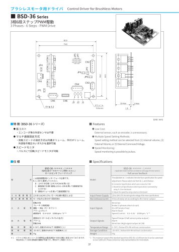
BSD-36 Series
Overview
The document presents technical details for the BSD-36 Series Control Driver designed for brushless motors. It features a 3-phase, 6-step PWM drive system optimized for cost efficiency and flexible speed control.
Features
- Low Cost: No need for external sensors such as encoders.
- Multiple Speed Setting Methods: Speed can be set via an internal volume, an external volume, or an external command voltage.
- Speed Monitoring: Speed feedback is available through pulse output.
Specifications
- Model Number: BSD-36-****-△*** (specific models referenced on motor pages).
- Speed Adjustment Interface: Options B, C, or D:
- B: Connector type using CN4
- C: Board terminal input via J1-J3
- D: On-board volume adjustment - Input Power Supply: 12V or 24V ±5%, depending on motor specifications.
- Maximum Continuous Current: Pre-set according to motor output.
- Input Signals: Direction control, brake (3-phase short circuit), start/stop (motor free), alarm reset, speed control voltage (0.5–5.5V, 1000 rpm/V).
- Output Signals: Speed output via hall sensor pulses, alarm signal, direction output (high signal for clockwise rotation).
- Operating Environment: 0–50°C, humidity below 85% RH without condensation.
- Storage Environment: -20–85°C, humidity below 85% RH without condensation.
- Weight: 55 grams.
Note: The standard maximum speed is set at 5,000 rpm but can be customized to exceed this upon request.
Functional Description
The driver uses a 3-phase bridge circuit controlled by a motor drive IC. Hall sensors provide feedback for commutation. Speed setting voltage controls the motor speed, with options for direct volume adjustment on the board or external command inputs. The driver includes inputs for start, brake, direction commands, and alarm reset. Outputs include speed pulses, fault signals, and direction indication.
Electrical Interface and Circuit Details
The document includes a detailed circuit diagram illustrating the power circuit, gain settings, motor drive IC, hall sensor connections, and F/V conversion. Key points include:
- Power voltage output is enabled only when jumper JP4 is shorted.
- Pads are provided for direct soldering of volume controls on the board.
- Input signals for start, brake, and direction commands are clearly defined.
- Output signals include pulse output for speed monitoring and fault output for alarms.
Environmental and Mechanical Considerations
- Designed for operation in moderate temperature and humidity conditions without condensation.
- Compact and lightweight design (55g) suitable for integration into various motor systems.
Summary: The BSD-36 series driver offers a cost-effective, flexible solution for brushless motor control with multiple speed setting options, integrated speed monitoring, and robust input/output signal handling. It supports various interface configurations and is adaptable for speeds beyond the standard 5,000 rpm limit through customization.
Catalog excerpts
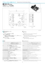
Control Driver for Brushless Motors 3 Phases - 6 Steps - PWM Drive ��.� External sensor, such as encoder, is unnecessary. ● Multiple Speed Setting Methods: Speed setting method can be selected from (1) Internal volume, (2) External Volume, or (3) External Command Voltage. Speed monitoring is possible by pulses. △は速度調整用インターフェース仕様です。 B、C、Dから選択してください。 B:コネクタ仕様(コネクタCN4を用いる) C:基板端子仕様(基板上のJ1~J3をを用いて直接指令を 入力する) D:基板ボリュームを用いて速度調整する Hall sensor feedback Input Power Supply Max Continuous Current 回転方向 ブレーキ(3相短絡) 号 運転 ー 停止(モータフリー) アラームリセット 速度指令 0.5~5.5V 1000rpm/V *1 Output Signals Temperature Range 速度出力(ホールセンサパルス出力) 回転方向 * 1 : ドライバ BSD-36 シリーズの標準品は最高速度が 5000 回転に設定されておりますが、 特注対応にて 5000 回転超の駆動が可能です。弊社までご相談ください。 ( Applicable model numbers are listed on each page of motor section ) ホールセンサ フィードバック
Open the catalog to page 1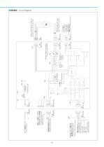
Command Input for Rotating Direction *Power voltage is output only when JP� is short - circuited Input to Reset Alarm Start Input Brake Input Voltage for Speed Setting Pad is prepared for direct soldering on board Vref 回転数設定電圧(�.�~�.�V) 基板上に直接ハンダ付け できるようにパッドを用意 モータ電源 DC+��V Gain Settings Power Circuit �-Phases Bridge Circuit
Open the catalog to page 2All CITIZEN CHIBA PRECISION CO., LTD. catalogs and technical brochures
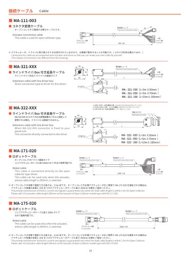 Connection cable
1 Page
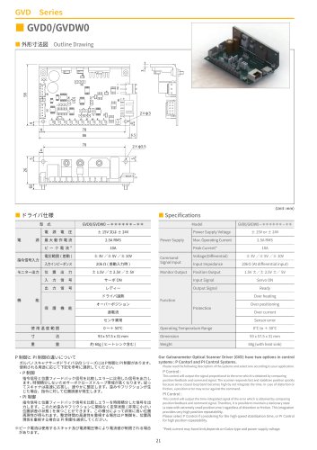 GVD Series
1 Page
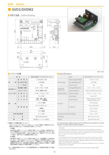 GVD2/GVDW2
1 Page
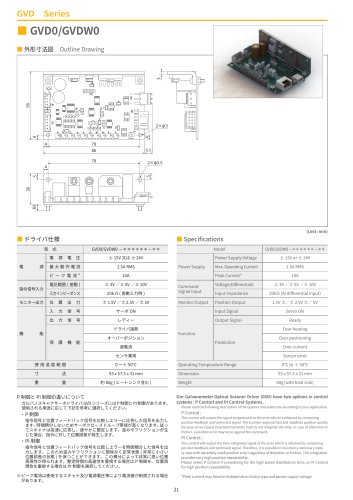 GVD0/GVDW0
1 Page
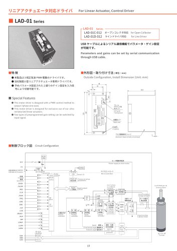 LAD-01 Series
2 Pages
 TSD-04-060
2 Pages
 Planetary Gearheads
3 Pages
 Linear Actuators
24 Pages
 Galvanometer Optical Scanners
28 Pages
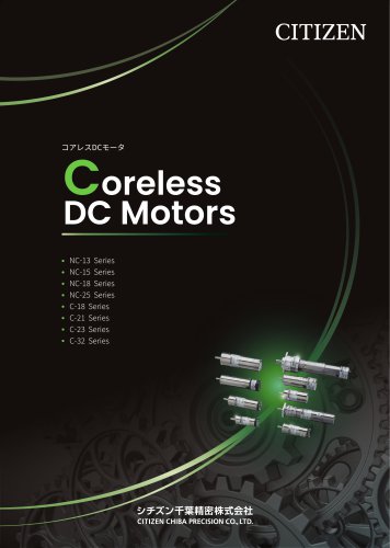 Coreless DC Motors
44 Pages
 Brushless Motors 2026
44 Pages
 Tachometer Generator
1 Page
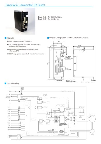
 Miniaturized AC Servomotors
16 Pages


Archived catalogs
 Galvanometer Optical Scanner
24 Pages
 Brushless Motor
36 Pages
 Linear Actuator
20 Pages
 Coreless DC Servo Motor
36 Pages
 Planetary Gearheads
5 Pages
- CITIZEN electric motor
- CITIZEN DC motor
- CITIZEN synchronous motor
- CITIZEN actuator
- Multipole motor
- Angular encoder
- CITIZEN linear actuator
- CITIZEN planetary gear reducer
- CITIZEN coaxial gear reducer
- CITIZEN electric actuator
- Incremental encoder
- Electromotor for industrial applications
- CITIZEN 24 V motor
- CITIZEN servomotor
- Incremental rotary encoder
- CITIZEN compact gear reducer
- Compact electromotor
- 2-pole motor
- CITIZEN 12 V motor