- Catalogs
- Cirrus Logic
- CS5351
CS5351
1 /23Pages

CS5351
1 /23Pages
Catalog excerpts
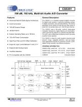
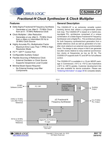
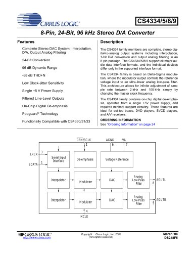
CS5351 108 dB, 192 kHz, Multi-bit Audio A/D Converter Features General Description Advanced Multi-bit Delta-Sigma Architecture 24-bit Conversion 108 dB Dynamic Range The CS5351 is a complete analog-to-digital converter for digital audio systems. It performs sampling, analogto-digital conversion, and anti-alias filtering. The device generates 24-bit values for both left and right inputs in serial form at sample rates up to 192 kHz per channel. The CS5351 uses a 5th-order, multi-bit, delta-sigma modulator followed by digital filtering and decimation, which removes the need for an external anti-alias filter. The ADC uses a differential architecture which provides excellent noise rejection. -98 dB THD+N System Sampling Rates up to 192 kHz 135 mW Power Consumption The CS5351 is ideal for audio systems requiring wide dynamic range, negligible distortion, and low noise. Such applications include A/V receivers, DVD-R, CD-R, digital mixing consoles, and effects processors. High-Pass Filter and DC Offset Calibration Supports Logic Levels Between 5 and 2.5 V ORDERING INFORMATION Single-Ended Analog Inputs CS5351-KZZ, Lead Free -10° to 70°C 24-pin TSSOP Overflow Detection Evaluation Board LRCK SDOUT Serial Output Interface Voltage Reference Digital Decimation Filter High Pass Filter Digital Decimation Filter High Pass Filter Copyright © Cirrus Logic, Inc. 2007 (All Rights Reserved)
Open the catalog to page 1
CS5351 1. CHARACTERISTICS AND SPECIFICATIONS (All Min/Max characteristics and specifications are guaranteed over the Specified Operating Conditions. Typical performance characteristics and specifications are derived from measurements taken at typical supply voltages and TA = 25°C.) SPECIFIED OPERATING CONDITIONS (GND = 0 V, all voltages with respect to 0 V.) Parameter Positive Analog Positive Digital Positive Logic Commercial (-KSZ/-KZZ) Automotive (-DZZ) Ambient Operating Temperature ABSOLUTE MAXIMUM RATINGS (GND = 0 V, All voltages with respect to ground.) (Note 1) Parameter Analog Logic Digital...
Open the catalog to page 4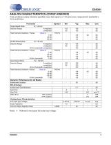
CS5351 ANALOG CHARACTERISTICS (CS5351-KSZ/KZZ) (Test conditions (unless otherwise specified): Input test signal is a 1 kHz sine wave; measurement bandwidth is 10 Hz to 20 kHz.) Parameter Single-Speed Mode Dynamic Range A-weighted unweighted Total Harmonic Distortion + Noise (Note 4) -1 dB -20 dB -60 dB Double-Speed Mode Fs = 96 kHz Dynamic Range A-weighted unweighted 40 kHz bandwidth unweighted Total Harmonic Distortion + Noise (Note 4) -1 dB -20 dB -60 dB 40 kHz bandwidth -1 dB Quad-Speed Mode Fs = 192 kHz Dynamic Range A-weighted unweighted 40 kHz bandwidth unweighted Total Harmonic Distortion...
Open the catalog to page 5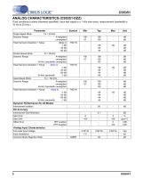
CS5351 ANALOG CHARACTERISTICS (CS5351-DZZ) (Test conditions (unless otherwise specified): Input test signal is a 1 kHz sine wave; measurement bandwidth is 10 Hz to 20 kHz.) Parameter Single-Speed Mode Dynamic Range A-weighted unweighted (Note 4) -1 dB -20 dB -60 dB Total Harmonic Distortion + Noise Double-Speed Mode Dynamic Range A-weighted unweighted 40 kHz bandwidth unweighted Total Harmonic Distortion + Noise (Note 4) -1 dB -20 dB -60 dB 40 kHz bandwidth -1 dB Quad-Speed Mode Fs = 192 kHz Dynamic Range A-weighted unweighted 40 kHz bandwidth unweighted Total Harmonic Distortion + Noise (Note...
Open the catalog to page 6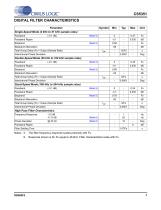
CS5351 DIGITAL FILTER CHARACTERISTICS Parameter Single-Speed Mode (2 kHz to 51 kHz sample rates) Passband Passband Ripple Stopband Stopband Attenuation Total Group Delay (Fs = Output Sample Rate) Interchannel Phase Deviation Double-Speed Mode (50 kHz to 102 kHz sample rates) Passband Passband Ripple Stopband Total Group Delay (Fs = Output Sample Rate) Stopband Attenuation Interchannel Phase Deviation Quad-Speed Mode (100 kHz to 204 kHz sample rates) Passband Passband Ripple Stopband Total Group Delay (Fs = Output Sample Rate) Stopband Attenuation Interchannel Phase Deviation High Pass Filter...
Open the catalog to page 7
Figure 1. Single-Speed Mode Stopband Rejection Figure 2. Single-Speed Mode Transition Band Figure 3. Single-Speed Mode Transition Band (Detail) Figure 4. Single-Speed Mode Passband Ripple Figure 5. Double-Speed Mode Stopband Rejection Figure 6. Double-Speed Mode Transition Band
Open the catalog to page 8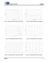
Figure 8. Double-Speed Mode Passband Ripple Figure 7. Double-Speed Mode Transition Band (Detail) Figure 11. Quad-Speed Mode Transition Band (Detail) Figure 10. Quad-Speed Mode Transition Band Figure 9. Quad-Speed Mode Stopband Rejection Figure 12. Quad-Speed Mode Passband Ripple
Open the catalog to page 9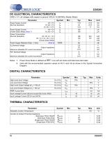
CS5351 DC ELECTRICAL CHARACTERISTICS (GND = 0 V, all voltages with respect to ground. MCLK=12.288 MHz; Master Mode) Parameter Power Supply Current (Normal Operation) Power Supply Current (Power-Down Mode) (Note 7) Power Consumption (Normal Operation) Power Supply Rejection Ratio (1 kHz) Filt+ Nominal Voltage Output Impedance Maximum allowable DC current source/sink Output Impedance Maximum allowable DC current source/sink Notes: 7. Power Down Mode is defined as RST = Low with all clocks and data lines held static. 8. Valid with the recommended capacitor values on FILT+ and VQ as shown in the...
Open the catalog to page 10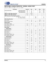
CS5351 SWITCHING CHARACTERISTICS - SERIAL AUDIO PORT (Logic "0" = GND = 0 V; Logic "1" = VL, CL = 20 pF) Parameter OVFL to LRCK edge setup time OVFL to LRCK edge hold time Output Sample Rate Single-Speed Mode Double-Speed Mode Quad-Speed Mode OVFL time-out on overrange condition Fs = 44.1, 88.2, 176.4 kHz Fs = 48, 96, 192 kHz MCLK Specifications MCLK Period MCLK Pulse Duty Cycle Master Mode SCLK falling to LRCK SCLK falling to SDOUT valid SCLK Duty Cycle Slave Mode Single-Speed Output Sample Rate SCLK Period LRCK Duty Cycle SCLK Duty Cycle SCLK falling to SDOUT valid SCLK falling to LRCK edge...
Open the catalog to page 11
SCLK output tmslr LRCK input LRCK output Figure 13. Master Mode, Left-Justified SAI Figure 14. Slave Mode, Left-Justified SAI SCLK input SCLK input tsclkw t slrd LRCK input t slrd LRCK input Figure 15. Master Mode, I²S SAI Figure 16. Slave Mode, I²S SAI Figure 17. OVFL Output Timing
Open the catalog to page 12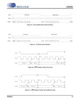
Left Channel Right Channel SCLK SDATA Figure 18. Left-Justified Serial Audio Interface Left Channel Right Channel SCLK SDATA Figure 19. I²S Serial Audio Interface Figure 20. OVFL Output Timing, I²S Format Figure 21. OVFL Output Timing, Left-Justified Format
Open the catalog to page 13All Cirrus Logic catalogs and technical brochures


Archived catalogs
 CS48DV2/6
2 Pages
 Mixed-Signal Audio Brochure
64 Pages


- Signal amplifying integrated circuit
- Power amplifying integrated circuit
- Compact converter
- Serial converter
- Industrial converter
- Measuring amplifier
- Voltage amplifier
- Serial receiver
- Digital amplifier
- Power converter
- Current amplifier
- Microcontroller
- Digital receiver
- Isolated converter
- Analog converter
- Fast converter
- Audio amplifying integrated circuit
- Video converter
- Programmable converter