- Catalogs
- Cirrus Logic
- CS5346
CS5346
1 /38Pages

CS5346
1 /38Pages
Catalog excerpts

CS5346 103-dB, 192-kHz, Stereo Audio ADC with 6:1 Input Mux ADC Features General Description Multi-bit Delta–Sigma Modulator The CS5346 integrates an analog multiplexer, programmable gain amplifier, and stereo audio analog-to-digital converter. The CS5346 performs stereo analog-to-digital (A/D) conve rsion of 24-bit serial values at sa mple rates up to 192 kHz. 103 dB Dynamic Range -95 dB THD+N Stereo 6:1 Input Multiplexer Programmable Gain Amplifier (PGA) – ± 12 dB Gain, 0.5-dB Step Size – Zero-crossing, Click-free Transitions Stereo Microphone Inputs – +32 dB Gain Stage – Low-noise Bias Supply Up to 192 kHz Sampling Rates Selectable 24-bit, Left-justified or I²S Serial Audio Interface Formats System Features +5 V Analog Power Supply, Nominal +3.3 V Digital Power Supply, Nominal Direct Interface with 3.3 V to 5 V Logic Levels Pin Compatible with CS5345 (*See Section 2 Level Translator High Pass Filter High Pass Filter Preliminary Product Information http://www.cirrus.com Register Configuration PCM Serial Interface Serial Audio Output Level Translator The CS5346 is available in a 48-pin LQFP package in Commercial (-40° to +85° C) grade. The CDB5346 Customer Demonstration board is also available for device evaluation and implementation suggestions. Please refer to “Ordering Information” on page 38 for complete details. The output of the PGA is followed by an advanced 5thorder, multi-bit delta-sigma modulator and digital filtering/decimation. Sampled data is transmitted by the serial audio interface at rates from 8 kHz to 192 kHz in either Slave or Master Mode. Integrated level translators allow easy interfacing between the CS5346 and other devices operating over a wide range of logic levels. I²C/SPI Control Data Interrupt A 6:1 stereo input multiplexer is included for selecting between line-level and microphone-level inputs. The microphone input path includes a +32 dB gain stage and a low-noise bias voltage supply. The PGA is available for line or microphone inputs and provides gain/attenuation of ±12 dB in 0.5 dB steps. Low-Latency Anti-Alias Filter Low-Latency Anti-Alias Filter Internal Voltage Reference Right PGA Output Stereo Input 1 Stereo Input 2 Stereo Input 3 Stereo Input 4 / Mic Input 1 & 2 Stereo Input 5 Stereo Input 6 This document contains information for a product under development. Cirrus Logic reserves the right to modify this product without notice. Copyright Cirrus Logic,
Open the catalog to page 1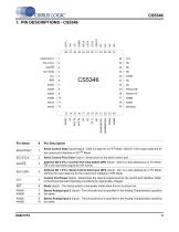
Serial Control Data (Input/Output) - SDA is a data I/O in I²C® Mode. CDOUT is the output data line for the control port interface in SPITM Mode. Serial Control Port Clock (Input) - Serial clock for the serial control port. Address Bit 0 (I²C) / Control Port Chip Select (SPI) (Input) - AD0 is a chip address pin in I²C Mode; CS is the chip-select signal for SPI format. Address Bit 1 (I²C) / Serial Control Data Input (SPI) (Input) - AD1 is a chip address pin in I²C Mode; CDIN is the input data line for the control port interface in SPI Mode. Control Port Power (Input) - Determines the required signal...
Open the catalog to page 5
Stereo Analog Input 1 (Input) - The full-scale level is specified in the Analog Characteristics specification table. Analog Ground (Input) - Ground reference for the internal analog section. Analog Power (Input) - Positive power for the internal analog section. Anti-alias Filter Connection (Output) - Antialias filter connection for the channel A ADC input. Anti-alias Filter Connection (Output) - Antialias filter connection for the channel B ADC input. Quiescent Voltage (Output) - Filter connection for the internal quiescent reference voltage. Positive Voltage Reference (Output) - Positive reference...
Open the catalog to page 6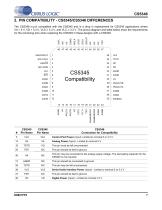
The CS5346 is p in compatible with the CS5345 and is a drop in replacement for CS5345 applications where VA = 5 V, VD = 3.3 V, VLS 3.3 V, and VLC 3.3 V. The pinout diagram and table below show the requirements for the remaining pins when replacing the CS5345 in these designs with a CS5346. Analog Power (Input) - Limited to nominal 5 V. This pin must be left unconnected. This pin should be tied to ground. This pin may be connected to the analog supply voltage. The decoupling capacitor for the CS5345 is not required. This pin should be connected to ground. This pin may be left unconnected....
Open the catalog to page 7
CS5346 3. CHARACTERISTICS AND SPECIFICATIONS RECOMMENDED OPERATING CONDITIONS AGND = DGND = 0 V; All voltages with respect to ground. Parameters Analog Digital Logic - Serial Port Logic - Control Port Ambient Operating Temperature (Power Applied) Commercial ABSOLUTE MAXIMUM RATINGS AGND = DGND = 0 V All voltages with respect to ground. (Note 1) Parameter VIND-S VIND-C Ambient Operating Temperature (Power Applied) Storage Temperature Input Current Analog Digital Logic - Serial Port Logic - Control Port (Note 2) Analog Input Voltage Digital Input Voltage Logic - Serial Port Logic - Control Port...
Open the catalog to page 8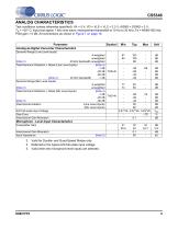
Test conditions (unless otherwise specified): VA = 5 V; VD = VLS = VLC = 3.3 V; AGND = DGND = 0 V; TA = +25° C; Input test signal: 1 kHz sine wave; measurement bandwidth is 10 Hz to 20 kHz; Fs = 48/96/192 kHz; PGA gain = 0 dB; All connections as shown in Figure 7 on page 18. Parameter Analog-to-Digital Converter Characteristics Dynamic Range (Line Level Inputs) A-weighted 97 103 unweighted 94 100 (Note 3) 40 kHz bandwidth unweighted 98 Total Harmonic Distortion + Noise (Line Level Inputs) (Note 4) -1 dB -95 -89 -20 dB THD+N -80 -60 dB -40 (Note 3) 40 kHz bandwidth -1 dB -92 Dynamic Range (Mic...
Open the catalog to page 9
CS5346 ANALOG CHARACTERISTICS CONT. Parameter Line-Level Input and Programmable Gain Amplifier A-weighted unweighted (Note 6) -1 dB THD+N -20 dB -60 dB A-weighted unweighted (Note 6) -1 dB THD+N -20 dB -60 dB Gain Range Gain Step Size Absolute Gain Step Error Maximum Input Level Input Impedance Selected inputs Un-selected inputs Selected Interchannel Input Impedance Mismatch Analog Outputs Dynamic Range (Line Level Inputs) Total Harmonic Distortion + Noise (Line Level Inputs) Dynamic Range (Mic Level Inputs) Total Harmonic Distortion + Noise (Mic Level Inputs) Frequency Response 10 Hz to 20 kHz...
Open the catalog to page 10All Cirrus Logic catalogs and technical brochures


Archived catalogs
 CS48DV2/6
2 Pages
 Mixed-Signal Audio Brochure
64 Pages


- Bourn And Koch signal amplifier
- Bourn And Koch power amplifier
- Compact converter
- Serial converter
- Industrial converter
- Measuring amplifier
- Voltage amplifier
- Serial receiver
- Digital amplifier
- Power converter
- Bourn And Koch microcontroller
- Current amplifier
- Isolated converter
- Digital receiver
- Analog converter
- Fast converter
- Audio amplifying integrated circuit
- Programmable converter
- Analog receiver