- Catalogs
- Cirrus Logic
- CS5343/44
CS5343/44
1 /21Pages

CS5343/44
1 /21Pages
Catalog excerpts

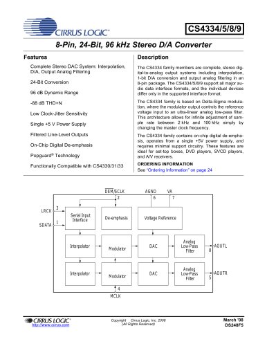
98 dB, 96 kHz, Multi-Bit Audio A/D Converter Features General Description Advanced Multi-Bit Architecture The CS5343/4 is a complete analog-to-digital converter for digital audio systems. It performs sampling, analogto-digital conversion, and anti-alias filtering, generating 24-bit values for both left and right inputs in serial form at sample rates up to 108 kHz per channel. 24-bit Conversion Supports Audio Sample Rates Up to 108 kHz 98 dB Dynamic Range at 5 V The CS5343/4 uses a 3rd-order, multi-bit Delta-Sigma modulator followed by a digital filter, which removes the need for an external anti-alias filter. -92 dB THD+N at 5 V Low-Latency Digital Filter The CS5343/4 also features a high-impedance sampling network which eliminates costly external components such as op-amps. High-Pass Filter to Remove DC Offsets Single +3.3 V or +5 V Power Supply The CS5343/4 is available in a 10-pin TSSOP package for both Commercial (-40° to +85° C) and Automotive grades (-40° to +105° C). The CDB5343 Customer Demonstration Board is also available for device evaluation and implementation suggestions. Please refer to the “Ordering Information” on page 19 for complete details. Power Consumption < 40 mW at 3.3 V Master or Slave Operation Slave Mode Speed Auto-Detect Master Mode Default Settings 256x or 384x MCLK/LRCK Ratio CS5343 Supports I²S Audio Format CS5344 Supports Left-Justified Audio Format The CS5343/4 is ideal for audio systems requiring wide dynamic range, negligible distortion and low noise, such as set-top boxes, DVD-karaoke players, DVD recorders, A/V receivers, and automotive applications. High-Z Sampling Network Low-Latency Digital Filters Internal Reference Voltages Single-Ended Analog Input High-Pass Filter High-Z Sampling Network Auto-detect MCLK Divider Serial Port Single-Ended Analog Input High-Pass Filter Low-Latency Digital Filters Copyright Cirrus Logic, Inc. 2006–2015 (All Rights Reserved) Slave Mode Auto-detect
Open the catalog to page 1
Serial Audio Data Output (Output) - Output for two’s complement serial audio data. Also selects Master or Slave Mode; See Section 4.1 on page 12 for details. Serial Clock (Input/Output) - Serial clock for the serial audio interface. Left Right Clock (Input/Output) - Determines which channel, Left or Right, is currently active on the serial audio data line. Master Clock (Input) - Clock source for the delta-sigma modulator and digital filters. Positive Voltage Reference (Output) - Positive reference voltage for the internal sampling circuits. AINL AINR Analog Input (Input) - The full-scale analog...
Open the catalog to page 3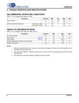
'CIRRUS LOGIC2. CHARACTERISTICS AND SPECIFICATIONS RECOMMENDED OPERATING CONDITIONS GND = 0 V, all voltages with respect to GND. Parameter GND = 0 V, all voltages with respect to GND. (Note 1) 1. Operation beyond these limits may result in permanent damage to the device. Normal operation is not guaranteed at these extremes. 2. Any pin except supplies. Transient currents of up to ±100 mA on the analog input pins will not cause SCR latch-up. 3. The maximum over/under voltage is limited by the input current.
Open the catalog to page 4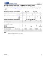
— CIRRI K LOGIC ANALOG CHARACTERISTICS - COMMERCIAL GRADE (-CZZ) Test conditions (unless otherwise specified): TA = 25° C; Input test signal is a 997 Hz sine wave through recommended inputs as seen in Figure 6 on page 14; source impedance less than or equal to 2.5 kQ; valid with FILT+ and VQ components as shown in Figure 3 on page 11; measurement bandwidth is 10 Hz to 20 kHz; Fs = 48 kHz or 96 kHz. Notes: 4. Referred to the typical full-scale input voltage
Open the catalog to page 5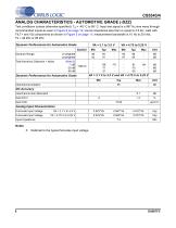
CS5343/4 ANALOG CHARACTERISTICS - AUTOMOTIVE GRADE (-DZZ) Test conditions (unless otherwise specified): TA = -40° C to 85° C; Input test signal is a 997 Hz sine wave through recommended inputs as seen in Figure 6 on page 14; source impedance less than or equal to 2.5 kQ; valid with FILT+ and VQ components as shown in Figure 3 on page 11; measurement bandwidth is 10 Hz to 20 kHz; Fs = 48 kHz or 96 kHz. Notes: 5. Referred to the typical full-scale input voltage
Open the catalog to page 6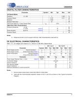
7. Device enters power-down mode when MCLK is held static. 8. Valid with the recommended capacitor values on FILT+ and VQ as shown in the Typical Connection Diagram.
Open the catalog to page 7
CS5343/4 DIGITAL CHARACTERISTICS Parameter
Open the catalog to page 8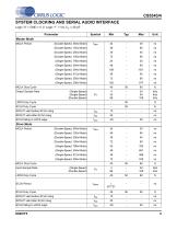
'CIRRUS LOGICSYSTEM CLOCKING AND SERIAL AUDIO INTERFACE Logic “0” = GND = 0 V; Logic “1” = VA, CL = 20 pF.
Open the catalog to page 9
t slrd LRCK t sclkw SCLK Figure 1. CS5343 I²S Serial Audio Interface t slrd LRCK t sclkw SCLK Figure 2. CS5344 Left-Justified Serial Audio Interface
Open the catalog to page 10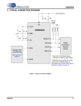
3. TYPICAL CONNECTION DIAGRAM 3.3 V to 5 V 0.1 µF Analog Input Conditioning Audio Processor/ System Clocks Pull-up to VA for Master Mode Pull-down to GND for Slave Mode Optional pull-up resistor for configuring clocks in Master Mode as described in the “Master Mode Speed Selection” section on page 13 Figure 3. Typical Connection Diagram
Open the catalog to page 11
CS5343/4 4. APPLICATIONS 4.1 Operation as Clock Master or Slave The CS5343/4 supports operation as either a clock master or slave. As a clock master, the left/right and serial clocks are synchronously generated on-chip and output on the LRCK and SCLK pins, respectively. As a clock slave, the LRCK and SCLK pins are always inputs and require external generation of the left/right and serial clocks. The selection of clock master or slave is made via a 10 kQ pull-up resistor from SDOUT to VA for Master Mode selection or via a 10 kQ pull-down resistor from SDOUT to GND for Slave Mode selection, as...
Open the catalog to page 12
— CIRRUS LOGIC 4.1.2 Master Mode Operation As clock Master, the CS5343/4 generates LRCK and SCLK synchronously on-chip. Table 3 shows the available sample rates and associated clock ratios in Master Mode. Table 5. Common MCLK Frequencies in Master and Slave Modes
Open the catalog to page 13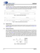
CS5343/4 4.2 Serial Audio Interface The CS5343 output is serial data in I2S audio format and the CS5344 output is serial data in Left-Justified audio format. Figures 4 and 5 show the PS and Left-Justified data relative to SCLK and LRCK. Additionally, Figures 1 and 2 display more information on the required timing for the serial audio interface format. For an overview of serial audio interface formats, please refer to Cirrus Application Note AN282. LRCK SCLK LRCK Left Channel Right Channel sclk jim,\JirLTLrLrLrLrL^^ SDATA 23122 9|8|7|6|5|4|3|2|1|q|^_23122 9|8|7|6|5|4|3|2|1 | 0__23122...
Open the catalog to page 14All Cirrus Logic catalogs and technical brochures


Archived catalogs
 CS48DV2/6
2 Pages
 Mixed-Signal Audio Brochure
64 Pages


- Bourn And Koch signal amplifier
- Bourn And Koch power amplifier
- Compact converter
- Serial converter
- Industrial converter
- Measuring amplifier
- Voltage amplifier
- Serial receiver
- Digital amplifier
- Power converter
- Bourn And Koch microcontroller
- Current amplifier
- Isolated converter
- Digital receiver
- Analog converter
- Fast converter
- Audio amplifying integrated circuit
- Programmable converter
- Analog receiver