
- Catalogs
- Cirrus Logic
- CS5340 101 dB, 192 kHz Stereo A/D Converter


- Products
- Catalogs
- News & Trends
- Exhibitions
CS5340 101 dB, 192 kHz Stereo A/D Converter

CS5340 101 dB, 192 kHz Stereo A/D Converter
- Advanced Multi-bit Delta-Sigma Architecture
- 24-bit Conversion supporting audio sample rates up to 192 kHz
- 101 dB Dynamic Range at 5 V
- -94 dB Total Harmonic Distortion plus Noise (THD+N)
- 90 mW Power Consumption
- High-Pass Filter to Remove DC Offsets
- Analog/Digital Core Supplies from 3.3 V to 5 V
- Supports Logic Levels between 1.8 V and 5 V
- Auto-detect Mode Selection in Slave Mode
- Auto-Detect MCLK Divider
- Pin Compatible with CS5341
The CS5340 is an analog-to-digital converter for digital audio systems, performing sampling, conversion, and filtering to produce 24-bit values at sample rates up to 200 kHz per channel. It uses a 5th-order Delta-Sigma modulator and digital filtering, eliminating the need for an external anti-alias filter. It is available in a 16-pin TSSOP package for commercial and automotive applications.
- Operating Conditions: Analog voltages of 3.3 V and 5.0 V
- Maximum Ratings: Exceeding limits may cause damage
- Analog Characteristics: Dynamic range and THD+N vary with voltage and mode
- Digital Filter Characteristics: Scale with sample rate (Fs)
- Single-, Double-, and Quad-Speed Modes
- Clock Master or Slave Operation
- Serial Audio Interface
- Power-Up Sequence
- Analog Connections
- Grounding and Power Supply Decoupling
- Synchronization of Multiple Devices
Figures illustrate stopband rejection, transition bands, and passband ripple for different modes. Tables detail specifications for speed modes, mode control, and master clock frequencies.
The document is a technical draft for the CS5340 ADC, detailing specifications, electrical characteristics, operational modes, and application guidelines.
The CS5340 supports various speed modes with sample rates from 2 kHz to 200 kHz, operating as a clock master or slave. Mode selection is via M0 and M1 pins, requiring a master clock (MCLK) with specific ratios for different modes.
Details include DC and digital characteristics, power supply requirements, power consumption, and voltage levels. The power supply rejection ratio is 65 dB, with parameters for normal and power-down modes.
Outlines timing requirements for the serial audio port, including MCLK specifications, SCLK duty cycles, and LRCK duty cycles for different modes. Describes timing for master and slave modes in I²S and left-justified formats.
Details each pin's function, such as mode selection, clock inputs, power inputs, and audio data outputs. A typical connection diagram is provided for optimal performance.
The CS5340 is suitable for various audio applications, supporting multiple speed modes and clock configurations. It can synchronize MCLK and LRCK signals across multiple devices for simultaneous sampling.
Emphasizes proper grounding and power supply decoupling for optimal performance. Recommendations include using clean supplies for VA and VL, and positioning decoupling capacitors close to the ADC.
Advises on analog input buffering and filtering to minimize noise and distortion, highlighting capacitor selection on the FILT+ pin for low-frequency distortion performance.
Defines dynamic range, THD+N, frequency response, interchannel isolation, gain mismatch, gain error, gain drift, and offset error.
Dimensions are provided in inches and millimeters, with notes on mold flash, dambar protrusion, and flat section dimensions. The controlling dimension is in millimeters.
Allowable Junction Temperature is up to 135°C with a Junction to Ambient Thermal Impedance of 75°C/W.
The CS5340 is available in commercial and automotive grades, with specific temperature ranges and packaging options. Recent revisions include updates to serial audio port characteristics, sample rate range, and output impedance specifications.
Cirrus Logic provides this information "AS IS" without warranty and advises verification before use. Products are not intended for critical applications involving potential risks of death or severe damage. Customers using products in such applications do so at their own risk and agree to indemnify Cirrus Logic from liability.
Catalog excerpts

CS5340 1. CHARACTERISTICSANDSPECIFICATIONS (AU Min/Max characteristics and spcifications are guaranteed over the Specified Operating Conditions. Typical performance characteristics and spcifications are derived from measurements taken at typical supply voltages and TA = 25°C.) SPECIFIEDOPERATINGCONDITIONS (GND = 0 V, ail voltages with respect to 0 V.) Parameter Symbol Min Typ Max Unit Power Supplies Analog VA 3.1 (Note 1 ) 5.25 V Digital VD 3.1 3.3 5.25 V Logic VL 1.7 3.3 5.25 V Ambient Operating Temp驩rature Commercial Tac -10 - 70 °C Automotive Tac -40 - 85 °C Notes: 1 This part is specrfed...
Open the catalog to page 4
CS5340 ANALOGCHARACTERISTICS-COMMERCIALGRADE Test Conditions (unless otherwise specified): Inpul test signal is a 1 kHz sine wave; measurement bandwidth is 10 Hz to 20 kHz. Dynamic Performance for Commercial Grade VA = 5V VA = 3.3 V Single-Speed Mode Fs =48 kHz Symbol Min Typ Max Min Typ Max Unit Dynamic Range A-weighted 95 101 - 92 98 - dB unweighted 92 98 89 95 - dB Total Harmonie Distortion + Noise (Note 5) THD+N -1 dB - -94 -88 Օ -91 -85 dB -20 dB - -78 - - -75 - dB -60 dB - -38 - - -35 - dB Double-Speed Mode Fs ■ 96 kHz Symbol Min Typ Max Min Typ Max Unit ._ Dynamic Range A-welghted 95 101...
Open the catalog to page 5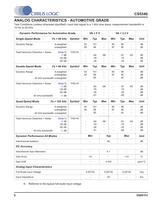
CS5340 ANALOGCHARACTERISTICS-AUTOMOTIVEGRADE Test Conditions (unless otherwise specified): Input test signal is a 1 kHz sine wave; measurement bandwidth is 10Hzto 20 kHz. Dynamic Performance for Automotive Grade VA = 5V VA = 3.3 V Single-Speed Mode Fs = 48 kHz Symbol Min Typ Max Min Typ Max Unit Dynamic Range A-welghted unwelghted 93 90 101 98 - 90 87 98 95 - dB dB Total Harmonie Distortion + Noise (Note 5) -1 dB -20 dB -60 dB THD+N - -94 -78 -38 -86 - -91 -75 -35 -83 CB dB dB DoubleSpeed Mode Fs = 96 kHz Symbol Min Typ Max Min Typ Max Unit Dynamic Range A-weighted unweighted 40 kHz bandwidth...
Open the catalog to page 6
CS5340 SCLK output LRCK output SDOUT Figure 13. Master Mode, LefUJustifted SAI Figure 14. Slave Mode, LefUJustified SAI SCLK output LRCK output SDOUT Figure 15. Master Mode. PS SAI Figure 16. Slave Mode, l*S SAI 12 DS601F2
Open the catalog to page 12
□RRUS LOGIC CS5340 2.PINDESCRIPTION Pin Name # Pin Description MO M1 1 16 Mode Slection (Inpu) - D鮩termines the operational mode of the device. MCLK 2 Master Clock {Input) - Clock source for the delta-sigma modulator and digital filters. VL 3 Logic Power {Input) - Positive power for the digital inpuf output. SDOUT 4 Sriai Audio Data Output (Output} - Output for two's complment s驩riai audk> data. GND 5.14 Ground {Input) - Ground rfrence. Must be connected to analog ground. VD 6 Digital Power {Input) - Positive power supply for the digital section. SCLK 7 S驩riai Clock {InputlOutput) - Sriai clock...
Open the catalog to page 13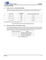
CS5340 4.APPLICATIONS 4.1 Single-, Double-, and Quad-Speed Modes The CS5340 can support output sample tates from 2 kHz to 200 kHz. The proper speed mode can be de-termined by the desired output sample rate and the extemal MCLK/LRCK ratio, as shown in Table 1. Speed Mode MCLK/LRCK Ratio Output Sample Rate Range (kHz) Single-Speed Mode 512x 43-50 256x 2-50 Doubte-Speed Mode 256x 86-100 128x 4-100 - Quad-Speed Mode 128x 172 - 200 64x" 100-200 Quad-Speed Mode. 64x onty avallable In Masler Mode. Table 1. Speed Modes and Ihe Associated Output Sample Rates (Fs) 4.2 Opթration as Either a Clock Master...
Open the catalog to page 15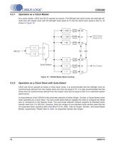
□RRUS LOGIC CS5340 4.2.1 Opration as a Clock Master Asa clock master,LRCK and SCLK operate as outputs. The left/right and sriai docks are internally de-rived from the master clock with the lett/right clock equal to Fs and the s驩riai clock equal lo 64xFs, as shown in Figure 18. -256 I Single fc Speed Doubte Speed I_Qliad- 00 0110 LRCK Output (Equal to Fs) *128 *64 Speed MCLK- +2 M1MO Single LI 00 Spcod Double Auto-Select *2 >01 10 SCLK Output Speed Quad Figure 18. CS5340 Master Mode Clockinq 4.2.2 Opration as a Clock Slave wlth Auto-Detect LRCK and SCLK operate as inputs in clock slave mode,...
Open the catalog to page 16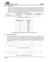
CS5340 4.2.3 Master Clock The CS5340 requires a Master clock (MCLK) which runs the internai sampling circuits and digital filters. There is also an internai MCLK divider which is automatically activated based on the speed mode and frequency of the MCLK. Table 3 shows a listing of the externat MCLK/LRCK ratios that are required. Table 4 lists some common audio output sample rates and the required MCLK frequency. Please note (hat not ail of the listed sample rates are supported when operating with a fast MCLK (512x, 256x, 128x for Single-. Double-, and Quad-Speed Modes, respectively). Single-Speed...
Open the catalog to page 17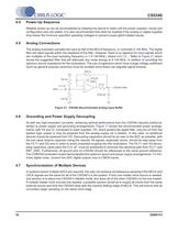
CIRRUS LOGIC CS5340 4.4 Power-Up Squence Reliable power-up can be accomplished by keeping the device in reset until the power supplies, docks and configuration pins are stable. It is also recommended tha reset be enabled if the analog or digital supplies drop below the minimum specified operating voltages to prevent power-glitch-related issues* 4.5 Analog Connections The analog modulatorsamplesthe input at half of the MCLKfrequency, or nominally 6.144 MHz. The digital filter will reject signais within the stopband of the filter. Howevert there is no rejection for input signais which are multiples...
Open the catalog to page 18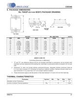
=^^F17KKUSLOG/CCS5340 6.PACKAGEDIMENSIONS 16LTSSOP(4.4mmBODY)PACKAGEDRAWING TOPVIEW INCHES MILLIMETERS NOTE MIN NOM MAX MIN NOM MAX A 0.043 ח 1.10 A1 0.002 0 004 0.006 0.05 ח 0.15 A2 0.03346 0.0354 0.037 0.85 0.90 0.95 b 0.00748 0.0096 0.012 0.19 0.245 0.30 2.3 D 0.193 0.1969 0.201 4.90 5.00 5.10 1 E 0.248 0.2519 0.256 6.30 6.40 6.50 E1 0.169 0.1732 0.177 4.30 4.40 4.50 1 e 0.026 BSC 0.65 BSC ח L 0.020 0.024 0.028 0.50 0.60 0.70 M 0' 4" 8" 0" 4" 8' JEDEC tt:MI>153 Controlltng Dimension is Millimeters 1, "D" and "ET are rfrence datums and do not included mold flash or protrusions. but do include...
Open the catalog to page 21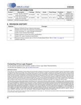
CS5340 7. ORDERINGINFORMATION Product Description Package Pb-Free Grade Temp Range Container Order ff CS5340 101 dB. 192 kHz. MurU-BH Audio A/D Converter 16-TSSOP YES Commercial -10° to +70° C Bulk CS5340-CZ2 Tape & Rel CS5340-CZZR CS5340 101 dB. 192 kHz. Multi-Brt Audio A/D Converter 16-TSSOP YES Automotive «40° to +85° C Bulk CS5340-DZZ Tape & Rel CS5340-DZ2R CDB5340 CS5340 Evaluation Board - - - - - CDB5340 8.REVISIONHISTORY Release Changes PP3 Remove CS5340-CZfrom Order驯ng Information Redefine Sriai Audio Port Switchlng Characteristics Correct dimension *e" under Package Dimensions Update...
Open the catalog to page 22All Cirrus Logic catalogs and technical brochures
 Professional Service Partners
12 Pages
 CS5343/44
21 Pages
 WM0011
233 Pages
 CS4970x4
31 Pages
 CS4953xx
37 Pages
 WM9081
103 Pages
 CS42L51
84 Pages
 CS42L42
184 Pages
 CS43198
137 Pages
 CS43131
156 Pages
 CS43130
137 Pages
 CS5351
23 Pages
 CS5346
38 Pages
 CS5341/42
21 Pages
 CS35L32
51 Pages
 CS35L00/01/03
34 Pages
 Energy Measurement Brochure
13 Pages


Archived catalogs
 CS48DV2/6
2 Pages
 Mixed-Signal Audio Brochure
64 Pages





- Signal amplifying integrated circuit
- Power amplifying integrated circuit
- Compact converter
- Serial converter
- Industrial converter
- Measuring amplifier
- Voltage amplifier
- Serial receiver
- Power converter
- Digital amplifier
- Microcontroller
- Current amplifier
- Digital receiver
- Isolated converter
- Analog converter
- Audio amplifying integrated circuit
- Fast converter
- Video converter
- Programmable converter