
- Catalogs
- Cirrus Logic
- CS42L51


- Products
- Catalogs
- News & Trends
- Exhibitions
CS42L51

CS42L51
Catalog excerpts
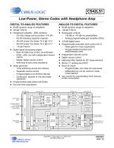
CS42L51 Low-Power, Stereo Codec with Headphone Amp DIGITAL-TO-ANALOG FEATURES ANALOG-TO-DIGITAL FEATURES 98-dB dynamic range (A-weighted) 98-dB dynamic range (A-weighted) Headphone amplifier - GND centered Analog gain controls – On-chip charge pump provides –VA_HP – No DC-blocking capacitor required – 46-mW power into stereo 16 @ 1.8 V – 88-mW power into stereo 16 @ 2.5 V – -75 dB THD+N Digital signal processing engine – Bass & treble tone control, de-emphasis – PCM + ADC mix with independent volume control – Master digital volume control – Soft ramp & zero-cross transitions Beep generator – Tone selections across two octaves – Separate volume control – Programmable on & off time intervals – Continuous, periodic or one-shot beep selections Programmable peak-detect and limiter Pop and click suppression 1.8 V to 3.3 V -88-dB THD+N – +32-dB or +16-dB mic preamplifiers – Analog programmable gain amplifier (PGA) +20-dB digital boost Programmable automatic level control (ALC) – Noise gate for noise suppression – Programmable threshold and attack/release rates Independent channel control Digital volume control High-pass filter disable for DC measurements Stereo 3:1 analog input MUX Dual mic inputs – Programmable, low noise mic bias levels – Differential mic mix for common mode noise rejection Very low 64 Fs oversampling clock reduces power consumption Serial Audio Input Serial Audio Output Hardware Mode or I2C & SPI Software Mode Control Data Beep Generator Digital Signal Processing Engine Switched Capacitor DAC and Filter Headphone Amp ‐ GND Centered Switched Capacitor DAC and Filter Headphone Amp ‐ GND Centered Volume Controls High Pass Filters Register Configuration Copyright Cirrus Logic, Inc. 2005–
Open the catalog to page 1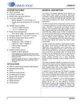
CIRRUS LOGIC SYSTEM FEATURES ♦ 24-bit converters ♦ 4-96-kHz sample rate ♦ Multibit delta-sigma architecture ♦ Low power operation - Stereo playback: 12.93 mW @ 1.8 V - Stereo record and playback: 20.18 mW @ 1.8 V ♦ Variable power supplies - 1.8-2.5 V digital & analog - 1.8-3.3 V interface logic ♦ Power down management - ADC, DAC, codec, mic preamplifier, PGA ♦ Software Mode (I2C™ and SPI™ control) ♦ Hardware mode (stand-alone control) ♦ Digital routing/mixes: - Analog out = ADC + Digital In - Digital out = ADC + Digital In - Internal digital loopback - Mono mixes ♦ Flexible clocking options -...
Open the catalog to page 2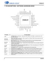
1. PIN DESCRIPTIONS - SOFTWARE (HARDWARE) MODE SCL/CCLK (I²S/LJ) Pin Description Left Right Clock (Input/Output) - Determines which channel, Left or Right, is currently active on the serial audio data line. SCL/CCLK (I²S/LJ) Analog Power For Headphone (Input) - Positive power for the internal analog headphone section. Charge Pump Cap Positive Node (Input) - Positive node for the external charge pump capacitor. Analog Ground (Input) - Ground reference for the internal headphone/charge pump section. Charge Pump Cap Negative Node (Input) - Negative node for the external charge pump capacitor. Negative...
Open the catalog to page 6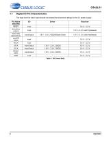
CS42L511.1 Digital I/O Pin CharacteristicsThe logic level for each input should not exceed the maximum ratings for the VL power supply. Pin Name SW/(HW) Table 1. I/O Power Rails
Open the catalog to page 8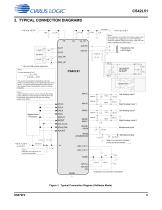
CS42L51 2. TYPICAL CONNECTION DIAGRAMS See Note 4 Note 4: Series resistance in the path of the power supplies must be avoided. Any voltage drop on VA_HP will directly impact the negative charge pump supply (VSS_HP) and result in clipping on the audio output . VA_HP AOUTB Headphone Out Left & Right SDIN SDOUT Right Analog Input 1 Left Analog Input 2 Right Analog Input 2 Left Analog Input 1 SCLK Digital Audio Processor Note 1: Resistors are required for I²C control port operation Speaker Driver Note 5 : Larger capacitors, such as 1.5 µF, improves the charge pump performance (and subsequent THD+N)...
Open the catalog to page 9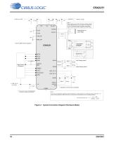
Headphone Out Left & Right Note 4: Series resistance in the path of the power supplies (typically used for added filtering) must be avoided. Any voltage drop on VA_HP will directly impact the negative charge pump supply (VSS_HP) and result in clipping on the audio output . Line Level Out Left & Right See Note 2 Speaker Driver MCLK SCLK LRCK AIN1A Digital Audio Processor * Capacitors must be C0G or equivalent DGND (1) Pull-up to VL (47 k for Master Mode. Pull-down to DGND for Slave Mode. Right Analog Input 1 Left Analog Input 1 Note 2 : This circuitry is intended for applications where the CS...
Open the catalog to page 10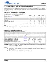
CS42L51 3. CHARACTERISTIC AND SPECIFICATION TABLES (All Min/Max characteristics and specifications are guaranteed over the Specified Operating Conditions. Typical performance characteristics and specifications are derived from measurements taken at nominal supply voltages and Ta = 25° C.) SPECIFIED OPERATING CONDITIONS (AGND=DGND=0 V, all voltages with respect to ground.) WARNING: Operation at or beyond these limits may result in permanent damage to the device. Normal operation is not guaranteed at these extremes. 2. Any pin except supplies. Transient currents of up to ±100 mA on the analog input...
Open the catalog to page 11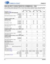
CS42L51ANALOG INPUT CHARACTERISTICS (COMMERCIAL - CNZ) (Test Conditions (unless otherwise specified): Input sine wave (relative to digital full scale): 1 kHz through passive input filter; Measurement Bandwidth is 10 Hz to 20 kHz unless otherwise specified. Sample Frequency = 48 kHz) Parameter (Note 4)
Open the catalog to page 12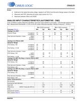
CS42L51Notes: 4. Referred to the typical full-scale voltage. Applies to all THD+N and Dynamic Range values in the table. 5. Measured with DAC delivering full-scale output power into 16 Q. 6. Measured between AINxx and AGND. ANALOG INPUT CHARACTERISTICS (AUTOMOTIVE - DNZ) (Test Conditions (unless otherwise specified): Input sine wave (relative to full scale): 1 kHz through passive input filter; Measurement Bandwidth is 10 Hz to 20 kHz unless otherwise specified. Sample Frequency = 48 kHz)
Open the catalog to page 13All Cirrus Logic catalogs and technical brochures


Archived catalogs
 CS48DV2/6
2 Pages
 Mixed-Signal Audio Brochure
64 Pages






- Signal amplifying integrated circuit
- Power amplifying integrated circuit
- Compact converter
- Serial converter
- Industrial converter
- Measuring amplifier
- Voltage amplifier
- Serial receiver
- Power converter
- Digital amplifier
- Digital converter
- Microcontroller
- Current amplifier
- Digital receiver
- Isolated converter
- Analog converter
- Audio amplifying integrated circuit
- Fast converter
- Video converter
- Programmable converter