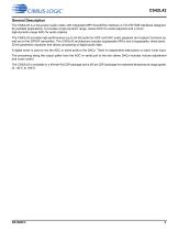
General Description: The CS42L42 is a low-power audio codec for portable applications, featuring interfaces like MIPI SoundWire and I2C/I2S/TDM. It supports 24-bit audio with stereo DAC for playback and mono ADC for capture, including sample-rate converters and a three-band parametric equalizer.
System Features: Key features include a stereo headphone output with 114-dB dynamic range, mono mic input, headset detection, system wake capabilities, and integrated power management.
Applications: Suitable for ultrabooks, tablets, smartphones, and digital headsets.
Functional Description: The codec includes a digital mixer, supports various sample rates, and features like wind-noise filter and headset type detection.
Specifications: Operating temperature range is -40°C to +85°C, available in 49-ball WLCSP and 48-pin QFN packages, supporting sample rates from 8 to 192 kHz.
Power Management: Operates from a 1.2-V supply or LDO from a 1.8-V supply, with a VP monitor for brownout detection.
Interface and Control: Features SoundWire interface, audio serial port, and S/PDIF Tx port with control-port operation and interrupt management.
PCB Layout Considerations: Recommendations include power supply and grounding strategies, and thermal pad considerations for QFN packages.
Characteristics and Specifications Overview: Detailed specifications include dynamic range, idle channel noise, interchannel isolation, load resistance, offset error, and THD+N.
Recommended Operating Conditions: Specifies voltage levels for charge pump, LDO regulator, and battery supply, with operational guarantees within these limits.
Absolute Maximum Ratings: Defines maximum allowable voltages and currents, with storage temperature range from -65°C to +150°C.
Filter Characteristics: Includes ADC and DAC filters, high-pass filters, and wind-noise digital filter specifications.
Output Fault Rating: Describes performance degradation over time under fault conditions.
HSIN-to-Serial Data Out Characteristics: Specifications for dynamic range and THD+N for HSIN inputs.
Functional Blocks: Includes analog input, digital mixer, equalizer, analog output, clocking architecture, SoundWire interface, serial ports, S/PDIF Tx port, sample-rate converters, headset interface, power management, control-port operation, resets, and interrupts.
Key Features: High dynamic range ADC path, digital-gain capability, soft ramping control, programmable attenuation, and three-band equalizer.
Recommendations: Use fully differential input configurations and proper attenuation settings to avoid clipping. Utilize power management features to reduce power consumption.
Three-Band Equalizer Overview: Describes a three-band equalizer system with filter coefficient management and analog output details.
Specifications and Equations: Provides equations for isolation and mute attenuation in headphone amplifiers, and details on Class H amplifier and power control options.
Clocking Architecture: Supports various clocking methods with an integrated fractional-N PLL, detailing start-up clocking and switching between clock sources.
SoundWire Interface: MIPI-compliant system for transporting control and audio data, with features like double data rate transmission and programmable frame structure.
Tables and Figures: Includes examples of PLL settings and illustrations of clocking architecture and SoundWire frame payload organization.
Critical Information: Internal PLL output must be between ~150 and ~300 MHz, and MCLKINT should be nominally 12 or 24 MHz.
Specifications and Control Word Bit Slot Fields: Describes modified NRZI scheme for BREL bit slot and control-word bit slot fields.
Register Access Response: Outlines SoundWire slave responses to commands in Control Word NAK and ACK fields.
Frame Synchronization and Slave Enumeration: Describes frame size and boundary determination and slave enumeration process.
Payload Transport: Explains payload data organization within a SoundWire frame.
Prepare/Enable Control: Procedure for enabling channels within a port.
SoundWire Memory Map and Register Banking: Describes device-level register address blocks and register banking.
Channel Shut-Down and Start-Up Procedures: Outlines procedures for channel shut-down and start-up.
SoundWire Interface and Bank Switching: Describes bank switch mechanism for applying changes at the next frame boundary.
Data Port Mapping and Register Access: Provides mapping of data ports and procedures for accessing registers outside the SoundWire IP.
APB Bridge Access Procedures: Special procedures for read/write commands to addresses outside the SoundWire IP.
Clock Stop Mode and Wake-Up Events: Describes Clock Stop Mode and conditions for wake-up events.
Programming Restrictions: Includes restrictions on writing to the active bank of a register and modifying nonbanked register fields.
SoundWire Interface Configuration: Guidelines for configuring data ports for 48- and 96-kHz operations using the SoundWire interface.
Sample Interval and Frame Rate: Provides examples of sample interval rates for 48 kHz and 96 kHz.
Audio Serial Port (ASP): Features an ASP for communication between system devices, supporting TDM, I2S, and left-justified audio interfaces.
Isochronous Serial-Port Operation: Describes isochronous mode and null-insert blocks for managing sample rates.
Specifications and Modes: Discusses handling of audio data streams using null sample insertion and removal.
Channel Controls: Outlines ASP channel controls for transmit and receive channels.
Isochronous Mode: Supported rates are 48k, 96k, and 192k.
50/50 Mode: Allows independent programming of left and right channels.
Serial Port Status: Describes status bits related to capture and render paths.
Power-Up and Power-Down Strategies: Recommended sequences for powering up and down playback, record paths, and serial ports.
S/PDIF Tx Port: Supports pass-through of encoded or PCM data.
Channel Coding and Keep-Alive Mode: Describes channel coding and Keep-Alive Mode for S/PDIF streams.
Sample-Rate Converters (SRCs): Bridge different sample rates at the serial ports within the digital-processing core.
Headset Interface: Provides an intelligent connection to external headsets, with features like programmable headset bias output and low-power standby mode.
Headset Type Detection: Detects headset pin configurations and sets appropriate connections via internal switches.
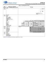
Plug Presence Detection: Detected using TIP_SENSE and RING_SENSE, supporting various plug types.
Tip and Ring Sense Debounce Configuration: Outlines configuration of debounce times for tip and ring sense.
Plug-Sense Gating: Describes use of TS_RS_GATE to manage plug detection.
Power-Supply Considerations: Highlights importance of power supply sequencing.
VP Monitor: Checks for brown-out conditions, ensuring VP remains above 3.0 V.
Control-Port Operation: Details operation of control-port registers via I2C or SoundWire interfaces.
Reset Options: Describes various reset options for the CS42L42.
SoundWire Status and Interrupts: Discusses behavior of SoundWire status bits during synchronization loss.
SoundWire Interrupts: Allows slaves to alert the master to abnormal events or error conditions.
Standard Interrupts: INT pin signals events within the device’s interrupt status registers.
Register Resets: Describes effects of resets on register fields.
Interrupt Source Types: Categorizes interrupt sources into condition-based and event-based types.
System Applications: Provides recommended procedures for standard operations.
Power-Up Sequence: Involves applying power supplies, configuring the ASP and SRC, enabling SCLK, and setting up the DAC and volume controls.
Power-Down Sequence: Outlines procedure for powering down the HP playback.
SoundWire Power Sequences: Describes power-up and power-down sequences for SoundWire.
Page 0x30 Read Sequence: Describes procedure for reading from Page 0x30.
PLL Clocking: Data-path logic operates in the MCLK domain, requiring PLL activation for non-standard SCLK frequencies.
Overview: Provides detailed technical procedure for the CS42L42 audio codec.
1. Standby Mode and Wake Detection: Describes procedure for entering and exiting Standby Mode.
2. Headset Type Detection Sequence: Describes procedure for detecting headset type.
3. Load Detection Sequence: Ensures proper compensation for the headphone amplifier.
4. External Output Switch Considerations: Provides guidelines for using external switches with the CS42L42 headset interface.
5. VD_FILT/VL ESD Diode: Recommendations for supplying VD_FILT and VL.
6. Register Quick Reference: Provides a quick reference table for register page addresses.
Interrupt Conditions and Status Registers: Outlines handling of interrupt conditions in the general interrupt status registers.
Interrupt Mask Registers: Determines whether specific events generate interrupts.
Control and System Registers: Manages various operational states.
Device Identification Registers: Provides unique identification for devices on the SoundWire bus.
Frame Control and Memory Access: Manages frame configurations and memory operations.
General Interrupt Status and Mask Registers: Manages interrupt conditions and their masking.
Memory Access Control: Managed through various registers, each with specific functions.
Memory Access Timeout: Controls timeout settings for memory access.
Memory Read Operations: Describes memory read operations and related registers.
SoundWire Data Port Descriptions: Describes registers for managing interrupts, control, and status.
Data Port Control: Manages data modes and word lengths.
Sample and Offset Control: Defines sample interval and block/subblock offsets within the SoundWire frame.
Global Registers: Includes Device ID and Revision ID registers.
MCLK Control: Manages internal sample rate by selecting divide ratio from MCLKINT.
Specifications: Details clock configuration, soft ramp rate, and procedures for slow start enable and I2C configuration.
Norms and Standards: Includes I2C stretch and timeout configurations.
Power Management: Describes power down controls and ring and tip sense configurations.
Recommendations: Includes headset detection configurations and best practices.
Headset Detection and Configuration: Outlines configuration settings for headset detection and type identification.
Headset Switch Control: Provides configuration for headset switch control.
Clocking Registers: Details clocking registers and configurations.
Interrupt Registers: Describes various interrupt status registers.
Key Parameters and Settings: Includes HSDET_CTRL settings and FSYNC_PULSE_WIDTH and FSYNC_PERIOD for ASP frame timing.
Recommendations: Ensure proper configuration of headset detection settings and clocking registers.
Current Sense Trip Point: Provides table listing tolerances for current sense trip points.
Wake Control (Address 0x1B71): Describes configuration of wake control settings.
ADC Disable Mute (Address 0x1B72): Details ADC automute settings.
Tip Sense Control 2 (Address 0x1B73): Configures operation of tip-sense circuit.
Miscellaneous Detect Control (Address 0x1B74): Covers detection mode settings and HS bias output control.
Mic Detect Control 1 (Address 0x1B75): Describes control of writable registers transfer between supply domains.
Mic Detect Control 2 (Address 0x1B76): Sets debounce time for S0 button detect.
Detect Status 1 & 2 (Addresses 0x1B77 & 0x1B78): Reports status of tip-sense circuit and HSBIAS mode.
Detect Interrupt Masks (Addresses 0x1B79 & 0x1B7A): Serve as masks for interrupt sources.
Headset Bias Control (Address 0x1C03): Configures HSBIAS settings.
ADC Control (Address 0x1D01): Covers ADC settings.
ADC Soft-Ramp Enable (Address 0x1D02): Enables digital soft ramp for ADC.
ADC Volume (Address 0x1D03): Sets ADC digital volume.
ADC Wind-Noise Filter and HPF (Address 0x1D04): Configures wind-noise filter and high-pass filter settings.
DAC Control (Addresses 0x1F01 & 0x1F06): Configures DAC signal polarity and output settings.
HP Output Load Configuration: Can be set to either 1 nF or 10 nF mode.
HPOUT Clamp Configuration: Determines whether HPOUT clamp is enabled or disabled.
DAC High-Pass Filter: Enabled by default, with a corner frequency of 0.935 Hz at 48 kHz.
HP Control Register: Includes settings for analog mute and full-scale volume control.
Class H Register: Configures adaptive power adjustment for HP output amplifiers.
Mixer Configuration: Allows input attenuation for various stereo digital inputs.
Equalizer Configuration: Filter coefficients can be read and written using specific registers.
AudioPort Interface Registers: Manage serial port receive and transmit configurations.
S/PDIF and SoundWire Control: Configures channel resolution for S/PDIF and SoundWire interfaces.
SRC Registers: Manage input and output sample rates for the SRC.
Soft Reset Reboot: Can be initiated to reinitialize internal settings after a SoundWire reset.
S/PDIF Control Registers: Manage S/PDIF transmit settings and characteristics.
ASP Transmit Registers: Configure ASP channel data requests and enable TDM TX channel output.
ASP Receive Registers: Enable ASP receive channels and configure double-rate mode settings.
ASP Receive DAI1 Channel Configuration: Details configuration of ASP Receive DAI1 channels.
PCB Layout Considerations: Guidelines for optimal PCB layout to enhance performance.
Digital Filter Response: Presents plots illustrating digital filter responses for ADC and DAC configurations.
Package Dimensions: Specifies dimensions for WLCSP and QFN packages.
Thermal Characteristics: Outlines thermal resistance parameters for QFN and WLCSP packages.
Ordering Information: Provides details on product ordering.
Revision History: Notes updates and changes made in different versions of the document.
Contact Information: For product inquiries, contact a Cirrus Logic Sales Representative via their website.
Important Notice: Cirrus Logic products and services are subject to terms and conditions of sale.
Product Use and Liability: Cirrus Logic products are not designed for critical applications.
Intellectual Property: This document is proprietary to Cirrus Logic.
Disclaimer: The document is provided "AS IS" without any warranty.
Trademarks: Cirrus Logic, the Cirrus Logic logo, and SoundClear are trademarks of Cirrus Logic.






 CS48DV2/6
 Mixed-Signal Audio Brochure