- Catalogs
- Cirrus Logic
- CS35L32
CS35L32
1 /51Pages

CS35L32
1 /51Pages
Catalog excerpts
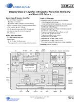
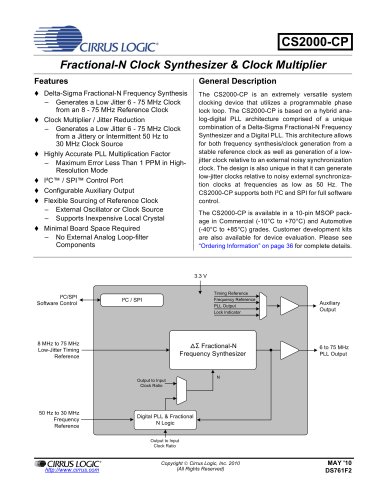
CS35L32 Boosted Class D Amplifier with Speaker-Protection Monitoring and Flash LED Drivers Mono Class D Speaker Amplifier • Two-level Class G operation: • Boosted: 5 V nominal • Bypassed: battery voltage is supplied directly • 2.5-mA quiescent current, monitors powered down • 1.7 W into 8 (@ 10% THD+N) • 102-dB signal-to-noise ratio (SNR, A-weighted) • Idle channel noise 25 Vrms (A-weighted) • 90% efficiency • Integrated dual LED drivers using the following: • Boost supply output voltage • Dual matched current regulators, 750 mA max each • Programmable setting for Flash Mode current: 50–750 mA, in 50-mA steps • Programmable setting for Flash-Inhibit Mode current: 50–350 mA, in 50-mA steps • Programmable setting for Movie Mode current: 150, 120, 100, 80, 60, 40, 20 mA • Programmable flash timer setting: 50–500 ms, in 25-ms steps • Dedicated pin for flash trigger (FLEN) • Dedicated pin for flash inhibit (FLINH) • Thermally managed through boost-voltage regulation Audio Input and Gain • One differential analog input • Speaker gain: • 9, 12, 15, and 18 dB and mute • Pop suppression, zero-crossing detect transitions Class D Power Stage SPKR SUPPLY Control, Sensing, and Fault Protection FLEN FLINH Current Mode Synchronous Boost Controller Soft Ramp SPKR SUPPLY Current Sense Bandgap Voltage Generation VREF Generation (Features continue on page 2) Flash LED Current Driver Temperature Sensor Overtemp Protection SPKOUT+ SPKOUT–/ VSENSE– Short Circuit Protection Power Budgeting Serial Port Clock Generation LRCK Range Scaling Serial Audio/Data Port GNDP VSENSE+ VSENSE– ISENSE+ ISENSE– ISENSE+ ISENSE–/ VSENSE+ I²C Control Port Level Shifters Copyright Cirrus Logic, Inc
Open the catalog to page 1
CS35L32 • Error status bit, including the following: • Stopped MCLK error • Protection: • Low battery detection with programmable thresholds • Latched overtemperature shutdown • VP UVLO error • Latched amplifier output short circuit shutdown • Overtemperature warning • LED short or open detection and LED driver shutdown • Overtemperature error • Flash inhibit LED current reduction • Boost converter overvoltage error • Low battery flash LED current reduction • Boost inductor current-limiting error • VP undervoltage lockout (UVLO) shutdown • Amplifier short-circuit error • Programmable boost inductor...
Open the catalog to page 2
CS35L32 The battery voltage, speaker voltage, and speaker current signals are monitored, digitized using converters, and serialized over an I2S bus. The speaker monitoring signals are part of a speaker-protection algorithm that is managed externally to the CS35L32. Outgoing data is sent over I2S with the CS35L32 in Slave or Master Mode. Battery voltage monitor data is accessible through I2C. An integrated dual LED driver operates up to two LEDs in Flash Mode or Movie Mode. A flash event is triggered by an external signal. A flash-inhibit event is triggered by an external signal, and causes...
Open the catalog to page 3
CS35L32 Table of Contents 1 Pin Descriptions . . . . . . . . . . . . . . . . . . . . . . . . . . . . . . . . . . . . . . 5 6 Register Quick Reference . . . . . . . . . . . . . . . . . . . . . . . . . . . . . 35 2 Typical Connection Diagram . . . . . . . . . . . . . . . . . . . . . . . . . . . 7 7 Register Descriptions . . . . . . . . . . . . . . . . . . . . . . . . . . . . . . . . 36 3 Characteristics and Specifications . . . . . . . . . . . . . . . . . . . . . . 8 7.1 Device ID A and B . . . . . . . . . . . . . . . . . . . . . . . . . . . . . . . . 36 Table 3-1. Recommended Operating Conditions...
Open the catalog to page 4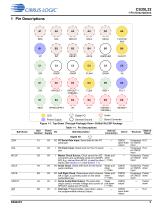
CIRRUS LOGIC SPKOUT+ SPKOUT-/ _Power Supply Figure 1-1. Top-Down (Through-Package) View—30-Ball WLCSP Package Ball Name Number Supply Ball Description Driver Receiver A1 VA I/O |2C Serial Data Input. Serial data for the PC serial port A2 VA I |2C Clock Input. Serial clock for the RC serial A5 VA I Master Clock Source. Clock source for A/D Weak pull- converters and audio/data serial port (ADSP). down MCLK|NT, derived from MCLK, is used for other H MQ) blocks (see Section 4.13 and Section 7.7). Hysteresis Pulled I/O Serial Clock. Serial shift clock for the serial audio interface Weak pull- CMOS...
Open the catalog to page 5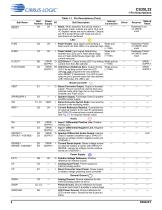
1 Pin Descriptions Table 1-1. Pin Descriptions (Cont.) Ball Name RESET Ball Power Internal I/O Ball Description Number Supply Connection — B3 VA I Reset. When asserted, the device enters a low-power mode, outputs are set to Hi-Z, and I²C register values are set to defaults. Outputs are Hi-Z except those with weak pull-ups or pull-downs as mentioned. State at Reset Hysteresis Low on CMOS input Receiver Flash Enable. Input signal commanding a Weak pullflash event into both LEDs. It is asserted high. down (~1 M Weak pullVA I Flash Inhibit. Input signal determining down whether the LEDs are in...
Open the catalog to page 6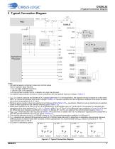
2 Typical Connection Diagram 2 Typical Connection Diagram 1 H Battery See Note 7 for LED and I2C addressing options. Applications Processor FLEN FLINH ISENSE–/ VSENSE+ SPKOUT+ LRCK SPKOUT–/ VSENSE– Notes: • All external passive component values are nominal values. Key for capacitor types required: * Use low ESR, X7R/X5R capacitors. ** Use low ESR, X7R capacitors. If no type symbol is shown next to a capacitor, any type may be used. • As required, add protection circuitry to ensure compliance with the absolute maximum ratings in Table 3-2. 1. CBST is a ceramic capacitor and derates at DC voltages...
Open the catalog to page 7
3 Characteristics and Specifications Table 3-1. Recommended Operating Conditions GNDA = GNDP = 0 V, all voltages with respect to ground. Device functional operation is guaranteed within these limits. Functionality is not guaranteed or implied outside of these limits. Operation outside of these limits may adversely affect device reliability. Parameters DC power supply Analog (and digital I/O and core) Battery External voltage applied to analog inputs powered by VA (IREF+, FILT+) 1 External voltage applied to analog inputs powered by SPKRSUPPLY (IN+, IN–, ISENSE+, ISENSE–,VSENSE+, VSENSE–) External...
Open the catalog to page 8All Cirrus Logic catalogs and technical brochures


Archived catalogs
 CS48DV2/6
2 Pages
 Mixed-Signal Audio Brochure
64 Pages


- Signal amplifying integrated circuit
- Power amplifying integrated circuit
- Compact converter
- Serial converter
- Industrial converter
- Measuring amplifier
- Voltage amplifier
- Serial receiver
- Digital amplifier
- Power converter
- Digital converter
- Current amplifier
- Microcontroller
- Digital receiver
- Isolated converter
- Analog converter
- Fast converter
- Audio amplifying integrated circuit
- Video converter
- Programmable converter