Catalog excerpts
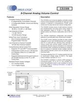
CS3308 8-Channel Analog Volume Control Features ♦ Complte Analog Volume Control - 8 Independently Controllable Channels - 3 Configurable Master Volume and Muting Controls ♦ Wide Adjustable Volume Range - -96 dB to +22 dB in % dB Steps ♦ Low Distortion & Noise - -112 dB THD+N - 123 dB Dynamic Range ♦ Noise-Free Level Transitions - Zero-Crossing Detection with Programmable Time-Out ♦ Low Channel-to-Channel Crosstalk - 120 dB Inter-Channel Isolation ♦ Comprehensive Serial Control Port - Supports I2C® and SPITM Communication - Independent Control of up to 128 Devices on a Shared 2-Wire PC or 3-Wire SPI Control Bus - Supports Individual and Grouped Control of all CS3308 Devices on the PC or SPI Control Bus ♦ Standard Power Supply Voltages - ±5 V Analog Supply - +3.3 V Digital Supply Description The CS3308 is an 8-channel digitally controlled analog volume control designed specifically for high-end audio systems. It features a comprehensive PC/SPI serial control port for easy device and volume configuration. The CS3308 includes arrays of well-matched resistors and complementary low-noise active output stages. A total adjustable range of 118 dB, in %dB steps, is spread evenly over 96 dB of attenuation and 22 dB of gain. The CS3308 implements configurable zero-crossing detection to provide glitch-free volume-level changes. The PC/SPI control interface provides for easy system integration of up to 128 CS3308 devices over a single 2-wire PC or 3-wire SPI bus, allowing many channels of volume control with minimal system controller I/O re-quirements. Devices may be controlled on an individual and grouped basis, simplifying simultaneous configuration of a group of channels across multiple devices, while allowing discrete control over all channels on an individual basis. The device operates from ±5 V analog supplies and has an input/output voltage range of ±3.65 V. The digital control interface operates at +3.3 V. The CS3308 is available in a 48-pin LQFP package in Commercial grade (-10° to 70° C). The CS3308 Cus-tomer Demonstration board is also available for device evaluation. Refer to "Ordering Information" on page 44 for complete details. 8-Channel Analog ■ Inputs PC/SPI Serial Control f CIRRUS LOGIC Copyright © Cirrus Logic, Inc. 2006 DECEMBER '06 http://www.cirrus.com (Al1 Rights Reserved) DS702F1
Open the catalog to page 1
CS3308 Pin Name # Pin Description OUT1 47 OUT2 44 OUT3 37 OUT4 34 Analog Outputs (Output) - The full-scale output level is specified in the Analog Characteristics specifi- OUT5 27 cation table. OUT6 24 OUT7 17 OUT8 14 REFI1 2 REFI2 41 REFI3 40 REFI4 REFI5 31 30 Reference In (Input) - Analog reference pin. REFI6 21 REFI7 20 REFI8 11 REFO1 48 REFO2 43 REFO3 38 REFO4 REFO5 33 28 Reference Out (Output) - Analog reference pin. REFO6 23 REFO7 18 REFO8 13 15, VA+ 25, 35, 45 Positive Analog Power (Input) - Positive power for the internal analog section. 16, VA- 26, 36, 46 Negative Analog Power...
Open the catalog to page 6
CS3308 2. CHARACTERISTICS AND SPECIFICATIONS All Min/Max characteristics and spcifications are guaranteed over the Specified Operating Conditions. Typical performance characteristics and specifications are derived from measurements taken at nominal supply voltages and TA = 25°C. SPECIFIED OPERATING CONDITIONS (DGND = 0 V; All voltages with respect to ground.) Parameters Symbol Min Nom Max Units DC Power Supplies: Positive Analog VA+ 4.75 5 5.25 V Negative Analog VA- -5.25 -5 -4.75 V Digital VD 3.1 3.3 3.5 V Ambient Operating Temperature (Power Applied) Ta -10 - +70 °C ABSOLUTE MAXIMUM...
Open the catalog to page 7
CS3308 ANALOG CHARACTERISTICS (Test conditions (unless otherwise specified): RS = 0; RL = 2kQ; CL = 20 pF; 10 Hz to 20 kHz Measurement Band-width) Parameter Symbol Min Typ Max Unit DC Characteristics Step Size - 0.25 - dB Gain Error (Vol = +22 dB) - ±0.5 - dB Gain Matching Between Channels (Vol = +22 dB) - ±0.1 - dB Input Resistance rin 8 10 - kQ Input Capacitance cin -10- pF AC Characteristics Total Harmonic Distortion + Noise (Note 3) THD+N - 0.00025 0.00063 % Dynamic Range 117 123 - dB Input/Output Voltage Range (THD+N < 1 %) Vfs (VA-) + 1.35 - (VA+) - 1.35 V Output Noise (Note 4) - 1.8...
Open the catalog to page 8
CS3308 DIGITAL INTERFACE CHARACTERISTICS Parameters Symbol Min Typ Max Units High-Level Input Voltage Vih 0.7 x VD - - V Low-Level Input Voltage Vil - - 0.2 x VD V High-Level Output Voltage at Io=2 mA Voh VD - 1.0 - - V Low-Level Output Voltage at Io=2 mA Vol - - 0.4 V Input Leakage Current lin - - ±10 |jA Input Capacitance - 8 - pF MUTE SWITCHING CHARACTERISTICS (Inputs: Logic 0 = DGND, Logic 1 = VD) Parameters Symbol Min Typ Max Units MUTE Active Pulse Width (Note 6) - 2 - - ms 6. The MUTE active state (low/high) is set by the MutePolarity bit in the Device Configuration 1 register (see...
Open the catalog to page 9
CS3308 CONTROL PORT SWITCHING CHARACTERISTICS - I2C FORMAT (Inputs: Logic 0 = DGND, Logic 1 = VD, CL = 20pF) Parameter Symbol Min Max Unit SCL Clock Frequency fscl - 100 kHz RESET Rising Edge to Start tirs 100 - ns Bus Free Time Between Transmissions tbuf 4.7 - Hs Start Condition Hold Time (prior to first clock pulse) thdst 4.0 - Hs Clock Low time tlow 4.7 - Hs Clock High Time thigh 4.0 - Hs Setup Time for Repeated Start Condition tsust 4.7 - Hs SDA Hold Time from SCL Falling (Note 7) thdd 0 - Hs SDA Setup time to SCL Rising tsud 250 - ns Rise Time of SCL and SDA trd - 1 Hs Fall Time SCL...
Open the catalog to page 10
CS3308 5.3.1 Recommended Power-Up Squence 1. Hold RESET low until the power supplies are stable. In this state, the control port is reset to its default settings. 2. Bring RESET high. The device will remain in a low power state with the PDN_ALL bit set by default. The control port will be accessible. 3. The desired register settings can be loaded while the PDN_ALL bit remains set. 4. Clear the PDN_ALL bit to initiate the power-up sequence. 5.3.2 Recommended Power-Down Sequence 1. Set the PDN_ALL bit to mute all channels and power-down all internal amplifiers. 2. If desired, hold RESET low...
Open the catalog to page 16All Cirrus Logic catalogs and technical brochures
-
Professional Service Partners
12 Pages
-
CS5343/44
21 Pages
-
WM0011
233 Pages
-
CS4970x4
31 Pages
-
CS4953xx
37 Pages
-
WM9081
103 Pages
-
CS42L51
84 Pages
-
CS42L42
184 Pages
-
CS43198
137 Pages
-
CS43131
156 Pages
-
CS43130
137 Pages
-
CS5351
23 Pages
-
CS5346
38 Pages
-
CS5341/42
21 Pages
-
CS35L32
51 Pages
-
CS35L00/01/03
34 Pages
-
Energy Measurement Brochure
13 Pages
Archived catalogs
-
CS48DV2/6
2 Pages
-
Mixed-Signal Audio Brochure
64 Pages


