
- Catalogs
- Cirrus Logic
- ClockCS2000 Family Generation and Multiplication/Jitter Reduction Solution


- Products
- Catalogs
- News & Trends
- Exhibitions
ClockCS2000 Family Generation and Multiplication/Jitter Reduction Solution
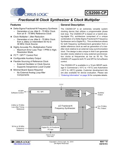
ClockCS2000 Family Generation and Multiplication/Jitter Reduction Solution
- Delta-Sigma Fractional-N Frequency Synthesis: Generates a low jitter 6 - 75 MHz clock from an 8 - 75 MHz reference clock.
- Clock Multiplier/Jitter Reduction: Produces a low jitter 6 - 75 MHz clock from a jittery or intermittent 50 Hz to 30 MHz clock source.
- Highly Accurate PLL Multiplication Factor: Maximum error less than 1 PPM in high-resolution mode.
- I²C/SPI Control Port: Allows for full software control.
- Configurable Auxiliary Output: Supports external oscillators or inexpensive local crystals.
- Minimal Board Space Required: No external analog loop-filter components needed.
The CS2000-CP is a versatile system clocking device utilizing a programmable phase lock loop. It combines a Delta-Sigma Fractional-N Frequency Synthesizer and a Digital PLL, enabling frequency synthesis and low-jitter clock generation from stable or noisy reference clocks. It supports I²C and SPI for software control and is available in commercial and automotive grades.
- Delta-Sigma Fractional-N Frequency Synthesizer: Allows precise frequency synthesis.
- Hybrid Analog-Digital Phase Locked Loop: Combines analog and digital techniques for enhanced performance.
- Timing Reference Clock Input: Supports internal timing reference clock divider and external reference clock.
- Frequency Reference Clock Input: Features CLK_IN skipping mode and adjustable loop bandwidth.
- Output to Input Frequency Ratio Configuration: Offers user-defined ratios and effective ratio configurations.
- SPI and I²C Control: Provides detailed control over device functions and configurations.
- Device I.D. and Revision: Identifies device and revision.
- Device Control: Includes unlock indicator and output disable options.
- Device Configuration: Allows selection of ratio modifiers and auxiliary output sources.
- High Resolution 12.20 Format and High Multiplication 20.12 Format: Provides methods for calculating user-defined ratios.
Details on package dimensions and ordering information are provided for commercial and automotive grades.
The document provides a detailed description of the CS2000-CP1 pin configuration. Key pins include VD for digital power, GND for ground reference, CLK_OUT for PLL clock output, and AUX_OUT for auxiliary output. Other important pins are CLK_IN for frequency reference clock input, XTO/XTI for crystal connections, and control port pins for I²C and SPI modes.
A typical connection diagram is provided, illustrating the necessary components and connections for the CS2000-CP2. It includes resistors for I²C operation, capacitors for power supply stabilization, and connections for low-jitter timing reference systems.
The document outlines recommended operating conditions, absolute maximum ratings, and DC electrical characteristics. Key parameters include power supply voltage, ambient operating temperature, and input/output voltage levels. The document warns against operating beyond specified limits to avoid device damage.
AC characteristics are detailed, including crystal frequency, reference clock input frequency, and PLL clock output frequency. The document specifies conditions for optimal performance, such as clock input pulse width and jitter measurements.
Switching characteristics for I²C and SPI formats are provided, detailing parameters like clock frequency, setup and hold times, and rise/fall times. These specifications ensure proper communication timing between the control port and external devices.
The document outlines the specifications for clock frequency ranges and configurations. The system clock (SysClk) should be between 8 MHz and 14 MHz, while the reference clock (RefClk) should be less than 50 MHz for XTI and 58 MHz for REF_CLK. The document also provides details on the normalized REF_CLK frequency and typical baseband jitter.
- Crystal Connections (XTI and XTO): An external crystal can be used to generate RefClk by connecting a 20 pF fundamental mode parallel resonant crystal between the XTI and XTO pins.
- External Reference Clock (REF_CLK): For operation with an external REF_CLK signal, connect XTI/REF_CLK to the reference clock source and leave XTO unconnected or pulled low through a 47 kΩ resistor to GND.
- Frequency Reference Clock Input (CLK_IN): Used in Hybrid PLL Mode to dynamically generate a fractional-N value for the Frequency Synthesizer.
- CLK_IN Skipping Mode: Allows the PLL to maintain lock even when the CLK_IN signal has missing pulses for up to 20 ms.
- Adjusting Minimum Loop Bandwidth: The loop bandwidth of the Digital PLL can be adjusted between 1 Hz and 128 Hz to affect the jitter transfer function.
- User Defined Ratio (RUD): Determines the input to output clock ratio, stored in a 32-bit format.
- Ratio Modifier (R-Mod): Used to internally multiply/divide the currently addressed RUD.
- Effective Ratio (REFF): Calculated as RUD multiplied by RMOD.
- Ratio modifiers that produce an overflow or truncation of REFF should not be used.
- The maximum and minimum allowable values for REFF are dictated by the frequency limits for both input and output clocks.
- Utilize the 12.20 High-Resolution format for RUD when the desired ratio is less than 4096 for better accuracy.
- Experiment with loop bandwidth settings to avoid system timing errors due to wandering between clocks.
The document includes figures illustrating the external component requirements for crystal circuits, CLK_IN removal scenarios, and the effects of loop bandwidth on clock domains. Table 1 summarizes the available options for the Ratio Modifier (R-Mod).
The document outlines the configuration and control of a device using various registers and control bits. Key sections include the Device Configuration 2 (Address 04h), Ratio Selection (RSel[1:0]), and Lock Clock Ratio (LockClk[1:0]). The Fractional-N Source for Frequency Synthesizer (FracNSrc) is also discussed, highlighting its role in frequency synthesis.
The Ratio Configuration Summary explains the user-defined ratio (RUD) and its storage in registers. The selection between static and dynamic ratio modes is determined by RSel[1:0] or LockClk[1:0] bits. The effective ratio (REFF) is calculated using the user-defined ratio and ratio modifier, corrected for internal dividers. The frequency synthesizer's fractional-N source can be selected manually or automatically.
The PLL clock output pin (CLK_OUT) provides a buffered output from the frequency synthesizer. The output can be set to high-impedance using the ClkOutDis bit. The document also describes conditions under which the PLL output may become unreliable.
The auxiliary output pin (AUX_OUT) can be mapped to various signals, controlled by the AuxOutSrc[1:0] bits. The document details the configuration of the auxiliary output and its potential phase differences from the main PLL clock output.
The document discusses the stability of clock outputs during reconfiguration, noting exceptions that may cause partial clock periods. It also outlines conditions that can cause the PLL to lose lock, affecting the clock signal.
Instructions for powering up the device include applying power, configuring operational settings, and ensuring the EnDevCfg1 and EnDevCfg2 bits are set.
The control port allows configuration via SPI or I²C interfaces. The document provides detailed instructions for both modes, including register access and the importance of maintaining default states for reserved registers.
A quick reference table lists register and bit names with default values, emphasizing the need to set EnDevCfg1 and EnDevCfg2 bits for normal operation.
Catalog excerpts
CIRRUS LOGC CS2000-CP Fractional-N Clock Synthesizer & Clock Multiplier Features General Description The CS2000-CP is an extremely versatile Systemclocking device that utilizes a programmable phase lock loop. The CS2000-CP is based on a hybrid ana-log-digital PLL architecture comprised of a unique combination of a Delta-Sigma Fractional-N Frequency Synthesizer and a Digital PLL. This architecture allows for both frequency synthesis/clock gnration from a stable r驩frence clock as well as gn驩ration of a low-jitter clock relative to an external noisy synchronization clock. The design is also unique in that it can gnrale low-jitter docks relative to noisy external synchroniza驭tion docks at frequencies as low as 50 Hz. The CS2000-CP supports both PC and SPI forfull software controL The CS2000-CP is available in a 10-pin MSOP package in Commercial (~10°C to +7(TC) and Automotive (-40°C to +85*C) grades, Customer development kits are also available for device ͩvaluation. Please see "Ordering Information" on page 36 for complte dtails. ♦ Delta-Sigma Fractional-N Frequency Synthesis - G詩nrtes a Low Jitter 6 - 75 MHz Clock from an 8 - 75 MHz R颩frence Clock ♦ Clock Multiplier / Jitter Rduction - G驩nrtes a Low Jitter 6 - 75 MHz Clock from a Jittery or Intermittent 50 Hz to 30 MHz Clock Source ♦ H颮ghly Accurate PLL Multiplication Factor Maximum Error Less Than 1 PPM in High-Resolution Mode ♦ l2Cי/SPIControlPort ♦ Configurable Auxiliary Output ♦ Flexible Sourcing of R٩frence Clock - External Oscillator or Clock Source Supports Inexpensive Local Crystal ♦ Minimal Board Space Required 闗 No External Analog Loop-filter Components 3,3 V PC/SPi Software ontrol PC/SPI PLLQuIpuI_ Auxiliary Output LOCK indicaux 8 MHz to 75 MHz Low-Jitter Timlng Rǩfrence Al Fractional-N Frequency Synthesizer 6 to 75 MHZ PLL Output Ortput to InpU C*x*Rato " 50 Hz to 30 MHz Frequency Rf驩rence CXrfjXillo tnpm ClOCK RatfO CIRRUS LOGIC* Copyright © Cirrus Logic, Inc 2010 MAY 10 http://www.dmjs.com(** Heseived) DS761F2
Open the catalog to page 1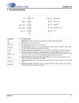
CS2000-CP 1. PIN DESCRIPTION VD GND CLKOUT AUX_OUT CLKJN 10 ~1 SDA/CDIN 2 9 SCL/CCLK 3 8 | ADO/CS 4 7 1XTI/REF CLK 5 6 XTO Pin Name # Pin Description VD 1 Digital Power (Input) - Positive power supply for the digital and anatog sections. GND 2 Ground (Input) - Ground rfrence. CLK_OUT 3 PLL Clock Output [Output) - PLL clock output. AUX_OUT 4 Auxiliary Output (Output) - This pin outputs a buffered version of one ot the input or output docks, or a status signal, depending on register configuration. CLKJN 5 Frequency R驩frence Clock Input (Input) - Clock input for the Digital PLL frequency rf驩rence....
Open the catalog to page 5
CS2000-CP 2. TYPICAL CONNECTION DIAGRAM V:v' Noie»; t. Rsistera raquirod for QDVrabon luf ( +3.3 V System MicroControlei VU SCUCCLK SDAi'COIN ADO/CS CS2000-CP Frequency Rf驩rence CLKJN )CTI/REF_CLK KTO CLK OUT To circuitry which requires a lowjrttcr clock 9 I I i I ♦ AUX OUT To other ciicuitry oi Mkfoconmltti GNO ^7 Low-Jrttef Timing Rfrence REF_CLK XTO Drystal i驗* XTI KTO *0 p^40pF Figure 1. Typical Connection Diagram 6 DS761F2
Open the catalog to page 6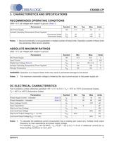
CS2000-CP 3. CHARACTERISTICS AND SPECIFICATIONS RECOMMENDED OPERATING CONDITIONS GND = 0 V; all voltages with respect to ground. (Note 1) Parameters Symbol Min Typ Max Units DC Power Supply VD 3.1 3.3 3.5 V Ambient Operating Temperature (Power Applied) Commercial Grade TAC -10 +70 °C Automotive Grade TAD -40 - +85 °C Notes: 1. Device functionality is not guaranteed or implied outside of these limits. Operation outside of these limits may adversely affect device reliability. ABSOLUTE MAXIMUM RATINGS GND = 0 V; all voltages with respect to ground. Parameters Symbol Min Max Units DC Power Supply...
Open the catalog to page 7
CS2000-CP AC ELECTRICAL CHARACTERISTICS Test Conditions (unless otherwise specified): VD = 3.1 V to 3.5 V; TA = -10°C to +70°C (Commercial Grade); TA = -40°C to +85°C (Automotive Grade); CL = 15pF. Parameters Symbol Conditions Min Typ Max Units Crystal Frequency Fundamental Mode XTAL fXTAL RefClkDiv[1:0] = 10 RefClkDiv[1:0] = 01 RefClkDiv[1:0] = 00 8 16 32 14 28 50 MHz MHz MHz Reference Clock Input Frequency fREF_CLK RefClkDiv[1:0] = 10 RefClkDiv[1:0] = 01 RefClkDiv[1:0] = 00 8 16 32 14 28 56 MHz MHz MHz Reference Clock Input Duty Cycle DREF_CLK 45 55 % Internal System Clock Frequency fSYS_CLK...
Open the catalog to page 8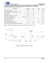
□RRUSLOGIC CS2000-CP CONTROL PORT SWITCHING CHARACTERISTICS- l2C FORMAT Inputs: Logic 0 = GND; Logic 1 = VD; C. = 20 pF. Parameter Symbol Min Max Unit SCL Clock Frequency - 100 kHz Bus Free-Time Belween Transmissions W 4.7 - MS Starl Condition Hold Time (pnor to firsl clock puise) thdst 4.0 - ps Clock Low Time w* 4.7 M8 Clock High Time 40 - Ms Setup Time for Repeated Starl Condition lsus( 4.7 - MS SDA Hold Time from SCL Falling (Note 12) Wj 0 ■ M8 SDA Setup Time to SCL Rising 250 - ns Rise Time of SCL and SDA tr - 1 MS Fall Time SCL and SDA *t - 300 ns Setup Time for Stop Condition 4.7 - MS Acknowledge...
Open the catalog to page 10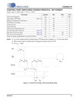
CS2000-CP CONTROL PORT SWITCHING CHARACTERISTICS - SPI FORMAT Inputs: Logic 0 = GND; Logic 1 = VD; CL = 20 pF. Parameter Symbol Min Max Unit CCLK Clock Ftequency - 6 MHz CCLK Edge to CS Falling (Note 13) W. 500 - ns CS Hkjh Time Between Transmissions tesn 1.0 - M* CS Falling to CCLK Edge tess 20 - ns CCLK Low Tirr.e »sd 66 - ns CCLK High Time tsen 66 - ns CDIN to CCLK Rising Setup Time 40 - ns CCLK Rising to DATA Hold Time (Note 14) tdh 15 - ns Rise Time of CCLK and CDIN (Note 15) 100 ns Fall Time of CCLK and CDIN (Note 15) te - 100 ns Delay frorn Suppty Voltage Stable to Control Port Ready *dpor...
Open the catalog to page 11
CS2000-CP 4. ARCHITECTURE OVERVIEW 4.1 Delta-Sigma Fractional-N Frequency Synthesizer The core of the CS2000 is a Delta-Sigma Fractional-N Frequency Synthesizer which has very high-resolu-tion for Input/Outpul dock ratios, low phase noise, very wjde range of output frequencies and Ihe ability to quickly tune to a new frequency. In very simplistic terms, the Fractional-N Frequency Synthesizer multiplies the Timing Rfrence Clock by the value of N to g驩nrale the PLL output dock, The desired output to input dock ratio is the value of N that is applied to the delta-sigma modulator (see Figure 7)....
Open the catalog to page 12All Cirrus Logic catalogs and technical brochures
 Professional Service Partners
12 Pages
 CS5343/44
21 Pages
 WM0011
233 Pages
 CS4970x4
31 Pages
 CS4953xx
37 Pages
 WM9081
103 Pages
 CS42L51
84 Pages
 CS42L42
184 Pages
 CS43198
137 Pages
 CS43131
156 Pages
 CS43130
137 Pages
 CS5351
23 Pages
 CS5346
38 Pages
 CS5341/42
21 Pages
 CS35L32
51 Pages
 CS35L00/01/03
34 Pages
 Energy Measurement Brochure
13 Pages


Archived catalogs
 CS48DV2/6
2 Pages
 Mixed-Signal Audio Brochure
64 Pages




- Signal amplifying integrated circuit
- Power amplifying integrated circuit
- Compact converter
- Serial converter
- Industrial converter
- Measuring amplifier
- Voltage amplifier
- Serial receiver
- Power converter
- Digital amplifier
- Digital converter
- Microcontroller
- Current amplifier
- Digital receiver
- Isolated converter
- Analog converter
- Audio amplifying integrated circuit
- Fast converter
- Video converter
- Programmable converter