
- Catalogs
- Circuit Design, Inc.
- VSWR checker Operation Guide

- Company
- Products
- Catalogs
- News & Trends
- Exhibitions
VSWR checker Operation Guide

VSWR checker Operation Guide
The VSWR Checker is a tool designed to ensure efficient antenna matching by comparing forward and reflected waves, displaying the return loss as a VSWR value. It helps in adjusting the antenna before permanent installation using an 8-stage LED display.
Features
- Easy impedance matching measurement without a network analyzer.
- Suitable for low power RF modules.
Specification
- Frequency range: 150 MHz to 1 GHz
- Impedance: 50Ω
- Connectors: SMA Male (module side), SMA Female (antenna side)
- RF input power range: 10 mW - 20 mW
- Battery: LR44 x 2
- Dimensions: 43.2 mm x 21.2 mm x 14.4 mm
Name and Function of Each Part
- SMA connectors for antenna and RF module connections.
- QR Code for accessing the product webpage.
- Battery box for 2 x LR44 batteries.
- Power switch and LED indicators for power and VSWR adjustments.
Method of Use
1. Connect the VSWR checker to the RF module.
2. Turn on the power and set the RF module to continuous transmission.
3. Adjust VR1 until the LED ADJ lights green.
4. Connect the antenna.
5. Observe which LED (1.2 to 4.0) lights up to determine VSWR.
Measurement Result
- VSWR 1.2 to 1.8 indicates good antenna impedance match.
- VSWR 2.5 to 4.0 indicates significant signal reflection and loss.
Important Notice
- Consult Circuit Design before ordering.
- Not intended for life support applications.
- Manufacturer is not responsible for transmission interruptions or secondary damages.
Cautions
- Avoid using near devices sensitive to electronic radio waves.
- Ensure power supply is within specified ratings.
- Avoid short circuits and reverse connections.
- Do not use in extreme environmental conditions.
Warnings
- Do not modify the equipment.
- Do not remove the product label.
Revision History
- Version 1.0, June 2020: First issue.
Catalog excerpts

OPERATION GUIDE Simple antenna matching indicator tool Operation guideVersion 1.0 (Jun. 2020) Circuit Design, Inc. 7557-1, Hotaka, Azumino-city, Nagano, 399-8303, JAPAN Tel: + +81 -(0)263-82-1024 Fax: + +81 -(0)263-82-1016 e-mail: [email protected] http://www.circuitdesign.jp OG VSWR Checker v10e 1 Circuit Design, Inc.
Open the catalog to page 1
OPERATION GUIDE
Open the catalog to page 2
CIH&UII MM. OPERATION GUIDE 1. Summary The VSWR checker is a simple antenna matching indicator tool that allows you to quickly and easily check the match between antenna and RF module. If antenna and RF module impedance is not matched, the transmitting signal cannot transfer the energy to the antenna and some energy will be lost due to reflection. To allow the antenna to emit efficiently, it is necessary to match the impedance of the antenna to the transmitter. This tool can compare the forward and reflected waves and display return loss as VSWR value allowing simple confirmation of impedance...
Open the catalog to page 3
cm&uii nimm. OPERATION GUIDE OG VSWR Checker v10e 4 Circuit Design, Inc.
Open the catalog to page 4
OPERATION GUIDE 5. Name and function of each part (i) (1) SMA connector (SMA Female) Connection to antenna (2) SMA connector (SMA Male) Connection to RF module (3) QR Code When accessed, this takes you to the webpage for the VSWR checker (page is in Japanese) (4) Battery box Use 2 x LR44 batteries. When inserting battery match to the “+” mark on the board top side (5) Power switch (6) Power supply LED When toggling the power switch, the LED glows red. (7) Control knob (VR1) Use for adjustment before taking measurement. (8) LED (ADJ) VR Led lights green when adjusting VR1 (9) LED (1.2 to 4.0)...
Open the catalog to page 5
cm&uii nimm. OPERATION GUIDE 6. Method of use Preparation ■RF module (MU-4-434, SLR-434M etc.) ■Conversion cable (if necessary) ■Antenna ■Blade type screwdriver Procedure OG VSWR Checker v10e 6 Circuit Design, Inc.
Open the catalog to page 6
OPERATION GUIDE mmi Dim inc. Measurement result VSWR 1.2 to 1.8 Return Loss is 10% or less. Antenna impedance shows good match. VSWR 2.5 to 4.0 A large amount of the transmitted signal is being reflected and is undergoing loss. Make adjustment such as increasing the area of the GND plane. For details refer to the video link below. https://youtu.be/SpX45xkIoes VSWR determination values Adjust to get as low VSWR as possible E.g. Transmission using 10 mW, VSWR at 3.0 means loss is 2.5 mW and amount radiated by antenna is 7.5 mW. OG VSWR Checker v10e 7 Circuit Design, Inc.
Open the catalog to page 7
OPERATION GUIDE Customers are advised to consult with Circuit Design sales representatives before ordering. Circuit Design believes the provided information is accurate and reliable. However, Circuit Design reserves the right to make changes to this product without notice. Circuit Design products are neither designed nor intended for use in life support applications where malfunction can reasonably be expected to result in significant personal injury to the user. Any use of Circuit Design products in such safety-critical applications is understood to be fully at the risk of the customer and...
Open the catalog to page 8
cm&uii nimm. OPERATION GUIDE The copyright of this manual belongs to Circuit Design, Inc. No part of this document may be reprinted, reproduced or modified without our permission OG VSWR Checker v10e 9 Circuit Design, Inc.
Open the catalog to page 9All Circuit Design, Inc. catalogs and technical brochures
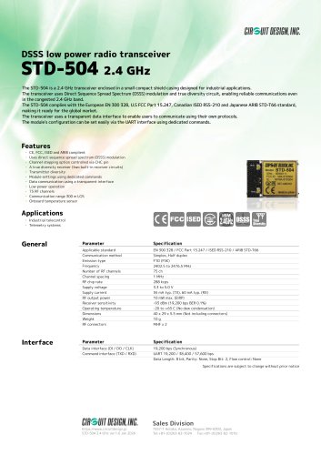 STD-504
1 Page
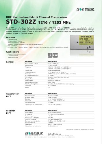 STD-302Z 1216/1252 MHz
1 Page
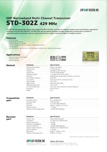 STD-302Z 429
1 Page
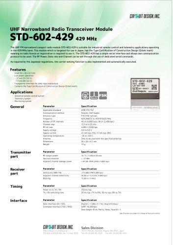 STD-602-429
1 Page
 Products data sheets
19 Pages
 Low power radio modules
1 Page
 STD-302Z: 434 MHz
1 Page
 MU-4-434
1 Page
 SLR-434M
1 Page
 WA-TX-03S, WA-RX-03S
1 Page
 LMD-401
1 Page
 STD-601
1 Page
 STD-601 400 MHz
1 Page
 STD-503
1 Page
 CDP-TX-07M, CDP-RX-07M
1 Page
 KST2.4S/KSR2.4
1 Page
 NK-2.4Y
1 Page
 ECB-03 & DCB-03
9 Pages
 KST2.4_Data Sheet
2 Pages


- Wireless remote control
- Remote control with buttons
- Cable assembly
- Circuit Design transceiver
- Outdoor housing
- Radio antenna
- Omnidirectional antenna
- On/off remote control
- Outdoor antenna
- Compact remote control
- External antenna
- Circuit Design radio transceiver
- Compact test kit
- Industrial modem
- Vehicle remote control
- Pump remote control
- Winch remote control
- Flexible electrical cable assembly
- Antenna for IoT applications
- Machinery remote control