- Catalogs
- Circuit Design, Inc.
- ECB-03 & DCB-03
- Company
- Products
- Catalogs
- News & Trends
- Exhibitions
ECB-03 & DCB-03
1 /9Pages

ECB-03 & DCB-03
1 /9Pages
Catalog excerpts

OPERATION GUIDE TEST board for RF module CDP series Operation Guide Version 2.0 (June 2020) This product requires electrical and radio knowledge for setup and operation. To ensure proper and safe operation, please read this operation guide thoroughly prior to use. Please keep this operation guide for future reference. CIRCUIT DESIGN, INC., 7557-1 Hotaka, Azumino-city Nagano 399-8303 JAPAN Tel: + +81-(0)263-82-1024 Fax: + +81-(0)263-82-1016 e-mail: [email protected] https://www.circuitdesign.jp
Open the catalog to page 1
OPERATION GUIDE GENERAL DESCRIPTION & FEATURES General description The evaluation board was developed to demonstrate and test the radio data modules CDP-TX02E/CDP-TX-02F and CDP-RX-02E/CDP-RX-02F. This set will save your time and effort for evaluation of CDP radio modules. It consists of a transmitter encoder board and receiver decoder board. In combination with the radio modules, it is a full 4 command radio remote control which can be practically used for various applications. Features 4 inputs & outputs, activated by 4 push buttons. Encoder & decoder circuit MSM6305 with 1024 user selectable...
Open the catalog to page 2
tURGIHimSIENM OPERATION GUIDE Batt (+,-) Power terminal Connect a 9V (006P) battery to the power supply clip. Please be careful with the polarity. Incorrect polarity may result in permanent damage of the boards. SW 1 - 4 (Operation buttons) Switches to transmit the each switching signal. With CDP-TX-02E/ CDP-TX-02F, the power is always supplied to the module during a main switch is ON. When SW 1- 4 is pushed, the module transmits the switching signal with ID number set at SW5. SW 5 (10 bits Address switch) Address switch for equipment. (1024 address can be set). This ID is needed to set same...
Open the catalog to page 3
OPERATION GUIDE CDP-RX DECODE BOARD (DCB-03) OPERATION Batt. (+,-) Power terminal Connect a 9V (006P) battery to the power supply clip. Please be careful with the polarity. Incorrect polarity may result in permanent damage of the boards. LED 1 - 4 LED turns on according to operation of the buttons on encode board. LED 5 LED brightness changes by the received signal strength. RSSI signal out from RX module is used. LED 6 LED shows the status of decode IC (MSM6305). LED on means that the radio signal is received and IC is working. SW 1 (10 bits Address switch) Address switch for equipment. (1024...
Open the catalog to page 4
OPERATION GUIDE
Open the catalog to page 5
OPERATION GUIDE CIRCUIT DIAGRAM (ECB-03)
Open the catalog to page 6
OPERATION GUIDE CIRCUIT DIAGRAM (DCB-03)
Open the catalog to page 7
OPERATION GUIDE Cautions As the product communicates using electronic radio waves, there are cases where transmission will be temporarily cut off due to the surrounding environment and method of usage. The manufacturer is exempt from all responsibility relating to resulting harm to personnel or equipment and other secondary damage. Do not use the equipment within the vicinity of devices that may malfunction as a result of electronic radio waves from the product. The manufacturer is exempt from all responsibility relating to secondary damage resulting from the operation, performance and...
Open the catalog to page 8
tURGIHimSIENM OPERATION GUIDE
Open the catalog to page 9All Circuit Design, Inc. catalogs and technical brochures
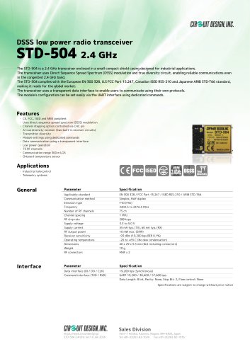 STD-504
1 Page
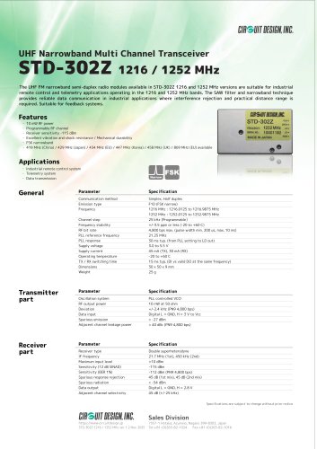 STD-302Z 1216/1252 MHz
1 Page
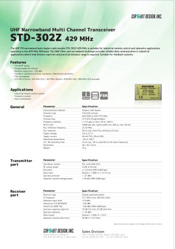 STD-302Z 429
1 Page
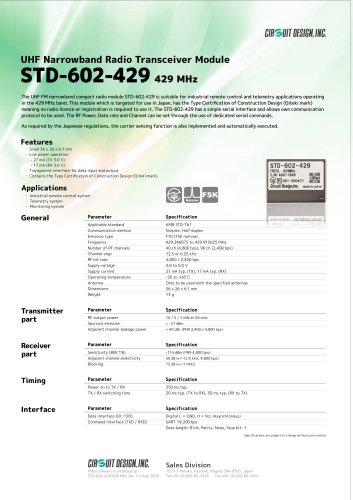 STD-602-429
1 Page
 Products data sheets
19 Pages
 Low power radio modules
1 Page
 STD-302Z: 434 MHz
1 Page
 MU-4-434
1 Page
 SLR-434M
1 Page
 WA-TX-03S, WA-RX-03S
1 Page
 LMD-401
1 Page
 STD-601
1 Page
 STD-601 400 MHz
1 Page
 STD-503
1 Page
 CDP-TX-07M, CDP-RX-07M
1 Page
 KST2.4S/KSR2.4
1 Page
 NK-2.4Y
1 Page
 KST2.4_Data Sheet
2 Pages
 VSWR checker Operation Guide
9 Pages


- Wireless remote control
- Remote control with buttons
- Transceiver module
- Liebherr cable harness
- Outdoor housing
- Radio antenna
- Omnidirectional antenna
- On/off remote control
- Outdoor antenna
- Compact remote control
- External antenna
- Radio transceiver module
- Industrial modem
- Vehicle remote control
- Compact test kit
- Pump remote control
- Winch remote control
- Flexible electrical cable assembly
- Machinery remote control
- 4-button remote control