Electric Fluid Heat Transfer Systems
Electric Fluid Heat Transfer Systems
1. Heat Transfer Fluid: Use the specified heat transfer fluid. Unauthorized mixing can cause incompatibility. Ensure proper cleaning and disposal when switching fluids.
2. Pipe Strain: Allow for expansion and contraction in piping to prevent misalignment and wear. Proper support is necessary to avoid stress.
3. Piping Restrictions: Avoid using smaller pipes than specified to prevent high differential pressure and pump failure. Use globe valves for balancing parallel flows.
4. Piping General: Regularly check for air, water, or foreign liquids. Install bleed valves to remove air pockets.
5. Expansion Tank Location: Mount the expansion tank at least 15 feet above the system. Regularly check vent lines.
6. Systems Mounted Above Process Equipment: Ensure sufficient NPSH to prevent vapor lock. Pressurize the expansion tank if necessary.
7. Pump Alignment and Adjustment: Proper alignment and adjustment of pumps are crucial. Regular checks are necessary.
8. Operating Temperature: Do not exceed the maximum allowable temperature to avoid degradation and system failure.
9. Insufficient Heat: Causes include low voltage, blown fuses, or system size inadequacy. Ensure proper insulation and check for flow restrictions.
10. Miscellaneous Problems: Address leaking joints and excessive leakage promptly. Use appropriate gaskets and connections.
Overview: This document provides technical guidance on troubleshooting and maintaining heat transfer systems, focusing on common issues, their causes, and corrective actions. It includes warranty information and limitations of liability from Chromalox.
Key Sections:
- Seal and Pump Issues: High temperature seals are designed to leak steam or water at a constant rate. Misalignment can lead to high leakage and failure. Avoid connecting cooling water to flush ports.
- Pump Bearing Failures: Causes include misalignment, cavitation, and high pressure due to poor quality fluid or contamination.
- System Spillage and Sludging: Spillage can occur due to an undersized expansion tank or air pockets. Sludging is caused by high heating element temperatures or improper materials.
- Troubleshooting Chart: Lists common problems, causes, and corrective actions, such as checking power sources and ensuring proper alignment.
- Warranty and Liability: Chromalox provides a warranty for defects with specific conditions. Claims must be made within specified timeframes.
Critical Information:
- Ensure proper alignment and connection of pumps and seals to prevent leaks and failures.
- Regularly check and maintain system components to avoid high pressure and cavitation issues.
- Follow manufacturer guidelines for system setup and operation to ensure warranty coverage.
Catalog excerpts
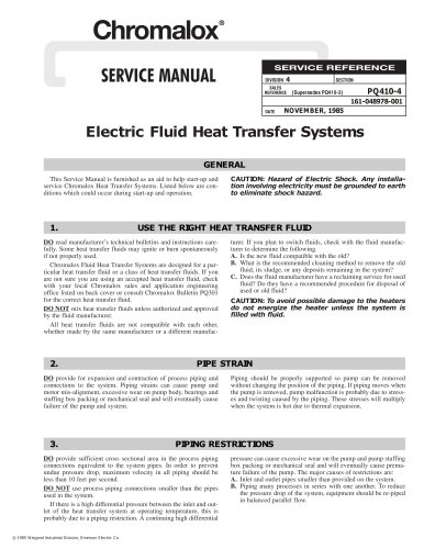
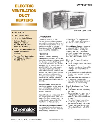
This Service Manual is furnished as an aid to help start-up andservice Chromalox Heat Transfer Systems. Listed below are con-ditions which could occur during start-up and operation. CAUTION: Hazard of Electric Shock. Any installa-tion involving electricity must be grounded to earthto eliminate shock hazard. > DO read manufacturers technical bulletins and instructions care-fully. Some heat transfer fluids may ignite or burn spontaneouslyif not properly used.Chromalox Fluid Heat Transfer Systems are designed for a par-ticular heat transfer fluid or a class of heat transfer fluids. If you are not sure you are using an accepted heat transfer fluid, checkwith your local Chromalox sales and application engineering office listed on back cover or consult Chromalox Bulletin PQ301for the correct heat transfer fluid. A. Is the new fluid compatible with the old? B. What is the recommended cleaning method to remove the oldfluid, its sludge, or any deposits remaining in the system? C. Does the fluid manufacturer have a reclaiming service for usedfluid? Do they have a recommended procedure for disposal of used or old fluid? CAUTION: To avoid possible damage to the heatersdo not energize the heater unless the system isfilled with fluid. DO NOT mix heat transfer fluids unless authorized and approvedby the fluid manufacturer.All heat transfer fluids are not compatible with each other,whether made by the same manufacturer or a different manufac- turer. If you plan to switch fluids, check with the fluid manufac-turer to determine the following. DO > provide for expansion and contraction of process piping andconnections to the system. Piping strains can cause pump andmotor mis-alignment, excessive wear on pump body, bearings and stuffing box packing or mechanical seal and will eventually causefailure of the pump and system.Piping should be properly supported so pump can be removedwithout changing the position of the piping. If piping moves whenthe pump is removed, pump malfunction is probably due to stress-es and twisting caused by the piping. These stresses will multiply when the system is hot due to thermal expansion. DO > provide sufficient cross sectional area in the process pipingconnections equivalent to the system pipes. In order to preventundue pressure drop, maximum velocity in all piping should beless than 10 feet per second. A. Inlet and outlet pipes smaller than provided on the system. B. Piping many processes in series with one another. To reducethe pressure drop of the system, equipment should be re-piped in balanced parallel flow. DO NOT use process piping connections smaller than the pipesused in the system.If there is a high differential pressure between the inlet and out-let of the heat transfer system at operating temperature, this isprobably due to a piping restriction. A continuing high differentialpressure can cause excessive wear on the pump and pump stuffingbox packing or mechanical seal and will eventually cause prema- ture failure of the pump. The major causes of restrictions are: > ҩ 1985 Wiegand Industrial Division, Emerson Electric Co. size="-2">
Open the catalog to page 1
3. The passageways or coring of a platen manifolded in series.These should be re-manifolded for parallel flow to give a minimum pressure drop. C. The use of globe valves in the system. Globe valves have amuch higher pressure drop than gate valves. Therefore use globe valves only for balancing parallel flows. DO D. Small inlet and outlet connections on customers process.Examples being: 1. The use of small rotary unions on roll applications. Theseshould be sized properly for the actual pumping rate to giveminimum pressure drop. 2. Small inlet and outlet nozzles on jacketed vessels or the useof...
Open the catalog to page 2
Note: If the expansion tank cannot be mounted above the highestpoint in the system, or if the system is going to operate above the boiling temperature of the heat transfer fluid, the expansion tank will have to be pressurized with air or nitrogen. This eliminates the possibility of heat transfer fluid flashing into vapor in the heater, at the point of high velocity in the system or at the suction of the pump which will cause the pump to vapor lock due to insufficient NPSH (net positive suction head). On hot oil heat transfer systems, this pressurizing is usually done with nitrogen as this eliminates...
Open the catalog to page 3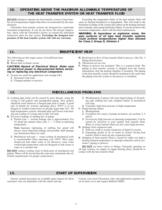
WARNING: Exceeding the temperature limits of the heat transfer fluid willcause its thermal breakdown or degradation. This will result in the formation of sludge in the system and carbon on the heating elements and eventually cause pump and heater failure. If you do not know this maximum temperature, check with the fluid manufacturer. In hazardous or explosive areas, thepipe surfaces of oil type heat transfer systemscould achieve temperatures higher than allowed for Class I, Group D, Division I. > The following are the major causes of insufficient heat: DO NOT attempt to operate any heat transfer...
Open the catalog to page 4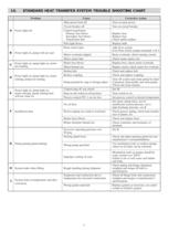
ProblemCauseCorrective Action A Power light offControl transformerPrimary fuse blownReplace fuse Secondary fuse blownReplace fuse Transformer badCheck and/or replacePilot light blownReplace bulb Float switch openAdd oil to system Main power feed offTurn on main power Circuit breaker offTurn on circuit breaker B Power light on, pump will not startIf no float switch, jumper terminals 4 & 5Motor overloads trippedReset overloads, check running currentMotor starter badCheck motor starter coil C Power light on, pump light on, motorMotor fuse blownReplace fuse, check motor overloadsnot runningMotor...
Open the catalog to page 5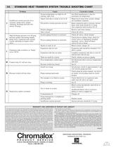
ProblemCauseCorrective Action System temperature too high for oilSee fluid manufacturers data forcausing vapor lockmaximum oil temperatureVapors lock due to steam or air in oilBleed air &steam from system, changeInsufficient suction pressure (0 oroil if problem continues J vacuum), pump noisy, gaugesNet positive suction pressure too lowRaise expansion tank to increase suctionvibrating, discharge pressure lowhead, static head should be 4-5 psig.(below 20 psig)(See expansion tank location No. 6)Strainer pluggedRemove and clean strainer Valve closedCheck all valvesHigh discharge pressure over 40...
Open the catalog to page 6All Chromalox catalogs and technical brochures
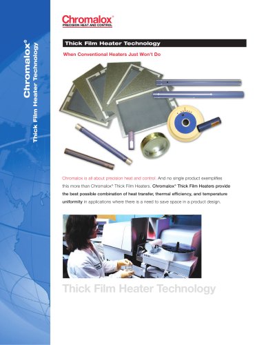 Thick Film Heater Technology
4 Pages
 Tubular V-Seal
2 Pages


- Digital temperature control
- Infrared heater
- Temperature control unit
- Steam boiler
- Adjustable thermostat
- Digital temperature control unit
- Temperature regulator
- Electric power radiant heater
- Air heater unit
- Digital temperature regulator
- Tubular electric heater
- Industrial radiant heating circuit
- Immersion heater
- Ceramic heating element
- Electric boiler
- Heating cable
- Electric air heater unit
- Circulating water temperature control unit
- PID temperature regulator