 Website:
Chr. Mayr GmbH + Co. KG
Catalog excerpts

Permanent magnet motors and servomotors
Open the catalog to page 1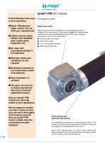
your reliable partner tendo®-PM DC motors If the following is the case in your machines: ■ asic “WindscreenB wiper motors” do not fulfil your requirements High-power gears ■ arbon service times, C lifetime and reliability play a particularly important role ■ n open and A unprotected design is not sufficient Many DC gear motors are designed to reduce speeds, and are not suitable for the transmission of high torques. tendo®-PM motors reliably transmit every torque possible based on the motor output and gear transmission, and run very quietly due to: ■ Generous gear dimensions ■ High tooth...
Open the catalog to page 2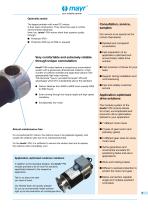
your reliable partner Optimally sealed The largest problem with most DC motors is their open construction. They cannot be used in critical environmental influences. Here, too, tendo®-PM motors show their superior quality through: Very comfortable and extremely reliable through unique commutation tendo®-PM motors feature a conspicuous commutation system with a generously dimensioned collector, a high number of collector lamellae and large-area carbons with appropriately high wear volumes. This technical “luxury” provides the tendo®-PM with advantages which lift it substantially above the...
Open the catalog to page 3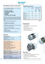
The optimum motor for every task The name tendo®-PM stands for a DC motor series which is mainly characterised by □ Modular concept □ Long service lifetime □ Reliability □ Quality □ Protection IP54 and IP65 tendo®-PM - these are motors with good concentricity even at the lowest speeds, good speed stability even when subjected to large load fluctuations, and a high degree of efficacy. They can also be used as direct drives. The following are available as standard: □ Voltages 24 V and 160 V (60 V) □ Speeds 2000 rpm and 3000 rpm. The tendo®-PM concept is modular. You will find exactly what...
Open the catalog to page 4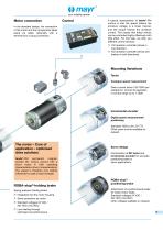
your reliable partner Motor connection In the standard design, the connection of the motor and the components takes place via cable, optionally with a terminal box or plug connection. A typical characteristic of tendo®-PM motors is that the speed follows the armature voltage in a linear manner, and the torque follows the armature current. This means that these motors can be controlled highly effectively with little effort. For this task, we offer you different control devices: ❐ Q transistor controller (drives in 1 ❐ Q transistor controller (drives and 4 brakes in both directions) Mounting...
Open the catalog to page 5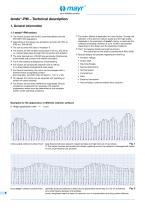
your reliable partner tendo®-PM – Technical description 1. General information 1.1 tendo®-PM motors ❐ he motors accord with the IEC recommendations and the T DIN VDE 0 530 regulations. ❐ epending on the design, the protection accords with IP54 or D IP65 acc. DIN 40 050. ❐ The coil accords with class of insulation F. ❐ he motors are self-cooled (cooling type IC 40 acc. IEC 34-6), T i.e. cooling takes place through free convection and radiation. ❐ he roller bearings acc. DIN 625 are generously dimensioned, T noise-tested and provided with lifetime lubrication. ❐ he carbon lifetime is...
Open the catalog to page 6
1.2 Gear for tendo®-PM motors 1.2.1 Worm gears Worm gears are universal-use hollow shaft gears. This means that they can be directly mounted onto the machine shaft to save space, or used to realise a shaft output via a one-sided or two-sided stub shaft. The worm gears are mainly used where high reductions are required with small construction volumes, or where damping characteristics are required in retroactive operation. In addition, they are suitable for use in cases where having the drive positioned at an angle to the machine provides advantages. The use of precision wheelsets and...
Open the catalog to page 7
your reliable partner tendo®-PM – Technical description 2.2.2 Worm gears The output-side flange dimensions of the worm gear are based on flange form “FT” for design B14, or on flange form “FF” for design B5 (DIN EN 50 347). In addition, screw-on surfaces are available on the facing and upper side, each featuring four fastening threads. On request, the gear can also feature stub shafts or special output shafts. On the worm gear motors, both the spatial position of the entire drive and the position of the electrical connection and flange or output shaft must be determined. See the...
Open the catalog to page 8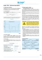
4.4 Operating Conditions The stated nominal powers (nominal torques) apply for Continuous operation (S1), max. 40 °C ambient temperature, form factor Ff = 1.05 and set-up height up to 1000 metres over sea level. The effective load torque (of the square mean value) over the time period must be smaller than or the same as the nominal torque. Mrms - MN Drive in anti-clockwise direction Quadrant III - U Braking in clockwise direction - n Quadrant IV
Open the catalog to page 9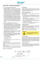
your reliable partner 4.5.1 Controller principle (thyristor/transistor) □ Thyristor controllers are characterised through their simple and robust construction. The motor voltage is obtained directly from the mains half-waves with a controlled bridge rectifier (phase angle control). The duration of the superimposed AC voltage totals at 10 ms approximately 3 times the electrical time constant of the motor from 2 .. 4 ms. The resulting ripple of the current and therefore the torque can be reduced through the use of a smoothing reactor. This is primarily of significance in connection with...
Open the catalog to page 10
your reliable partner tendo®-PM - Technical description5. Calculation guidelines M, Spindle drive Motor speed Load torque (= torque during constant speed) Translatory mass moment of inertia Rotatory mass moment of inertia (for steel) JR = 7.7 x d4 x l x 10-13 For aluminium, the value is to multiplied by a factor of 0.35 Sum of reduced mass moments of inertia Acceleration torque or braking torque Mb= f (nM) (load and friction-free) Acceleration torque or braking torque Mb= f (v) (load and friction-free) Acceleration time or braking time tB= f (nM) (with load torque) Acceleration time or...
Open the catalog to page 11All Chr. Mayr GmbH + Co. KG catalogs and technical brochures
-
Test stand technology
16 Pages
-
Steel industry
12 Pages
-
Wind energy
24 Pages
-
Stage Technology – Applications
20 Pages
-
Elevator Brakes
24 Pages
-
Machine Tool Components
20 Pages
-
Robotics and Automation
20 Pages
-
EAS®-Sp/Sm/Zr
24 Pages
-
EAS®-smartic®
12 Pages
-
EAS®-reverse
4 Pages
-
EAS®-HTL
8 Pages
-
EAS®-HT
28 Pages
-
EAS®-HSE
16 Pages
-
ROBA®-capping head
12 Pages
-
EAS®-dutytorque
8 Pages
-
ROBA®-contitorque
12 Pages
-
ROBATIC®
60 Pages
-
EAS®-axial
24 Pages
-
ROBA®-drive-checker
4 Pages
-
ROBA®-DS (heavy duty)
80 Pages
-
ROBA®-ES
32 Pages
-
smartflex®
8 Pages
-
ROBA®-DS for torque transducers
16 Pages
-
ROBA®-DS (steel)
80 Pages
-
ROBA®-DS (servo)
80 Pages
-
ROBA®-slip hub
24 Pages
-
EAS®-compact® F
32 Pages
-
EAS®-compact®
40 Pages
-
ROBA®-takt
60 Pages
-
ROBA®-SBCplus
4 Pages
-
ROBA®-secustop
8 Pages
-
ROBA®-twinstop®
12 Pages
-
ROBA®-duplostop®
12 Pages
-
ROBA®-alphastop®
8 Pages
-
ROBA®-topstop®
24 Pages
-
ROBA-stop®-stage
4 Pages
-
ROBA-stop®-S
12 Pages
-
ROBA®-quick
60 Pages
-
ROBA®-linearstop H
16 Pages
-
ROBA®-linearstop E
16 Pages
-
ROBA®-guidestop
32 Pages
-
ROBA®-diskstop®
8 Pages
-
ROBA-stop®-M Eco
4 Pages
-
ROBA-stop-M servo pitch
8 Pages
-
ROBA®-linearstop P
16 Pages
-
ROBA-stop®-silenzio®
28 Pages
-
ROBA-stop®-M
24 Pages
-
ROBA®-servostop® Lean
12 Pages
-
ROBA®-servostop® Cobot
12 Pages
-
ROBA®-servostop® Classic
12 Pages


