- Catalogs
- Chr. Mayr GmbH + Co. KG
- EAS®-axial
EAS®-axial
1 /24Pages

EAS®-axial
1 /24Pages
Catalog excerpts

your reliable partner EAS®-axial Overload protection for linear movements
Open the catalog to page 1
your reliable partner EAS®-axial – Two-directional overload protection ●● Limits tensile and compressive forces. ●● High quality materials, hardened functional components and superior manufacturing precision guarantee excellent repetitive accuracy of the set force and increase the service lifetime. ●● Backlash-free force transmission with high axial rigidity. ●● Immediate force interruption in the event of overload. ●● Stepless adjustment of the release force. ●● Free stroke in both tensile and compressive direction can be defined by the user. ●● EAS®-axial with integrated limit switch emits...
Open the catalog to page 2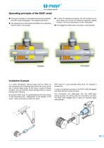
your reliable partner Operating principle of the EAS®-axial ●● If the pre-set tensile or compressive forces are exceeded, the EAS®-axial disengages in the respective direction. ●● The release force is individually adjustable via an adjusting ring and mayr®-cup springs. ●● In case of overload occurrence, the bolt carries out an axial stroke and moves the switching segments radially outward. The force transmission is then interrupted. ●● Re-engagement takes place manually or automatically. Installation Example In a crank mechanism, various forces have an effect on the connecting rod. Extremely...
Open the catalog to page 3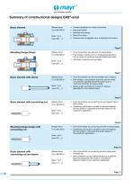
Basic element Release force: • Overload protection for linear movements. High axial rigidity. Backlash-free design. Rapid force drop. Overload can be signalled via a contactless limit switch. Mounting flange design Release force: • Force transmitted via bolts and mounting flange. Free strokes in tensile and / or compressive directions can be varied via customer-supplied attachment parts. Application example: feed carriages. Basic element with sleeve Release force: • Force transmitted via bolt and threaded end of sleeve. Free strokes in compressive directions can be varied via customer-supplied...
Open the catalog to page 4
o mayr your reliable partner _ Basic element with guide rod Release force: 75 to 300 000 N Force transmitted via bolt and tapped hole on the housing. Guide rod length is suitable for accommodating the free stroke in tensile direction based on the customer’s application. Page 12 Mounting flange design with Release force: • Force transmitted via bolts and mounting flange. guide rod 75 to 300 000 N • Guide rod length is suitable for accommodating the free stroke in tensile direction based on the customer’s application. Release force: • Force transmitted via bolt and sleeve-side threaded pin. Both...
Open the catalog to page 5
U mayr your reliable partner Type 300._ _0 Sizes 1 to 8 Cable length approx. 2 m, 0 3,5 mm Thread and centering as on the other side We reserve the right to make dimensional and constructional alterations. 1) Additional sizes for lower or higher release forces on request. Re-engagement force = 20 - 25 % of the release force. 2) Hi max: free stroke in tensile direction; H2 max: free stroke in compressive direction (larger free strokes on request) 3) EAS®-axial without limit switch - delivery with bushing (M8 or M5) 4) See Technical Data, release forces Fa Sizes Release force 4) Limit switch Low...
Open the catalog to page 6
your reliable partner Mounting flange design We reserve the right to make dimensional and constructional alterations. 1) Additional sizes for lower or higher release forces on request. Re-engagement force = 20 - 25 % of the release force. 2) Hi maX' free stroke in tensile direction; H2 max: free stroke in compressive direction (larger free strokes on request) 3) EAS®-axial without limit switch - delivery with bushing (M8 or M5) 4) See Technical Data, release forces Fa Sizes Release force 4) Limit switch Low 4 0 Without limit switch 3) to Medium 5 1 With integrated 8 High 6 limit switch Example:...
Open the catalog to page 7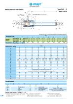
your reliable partner We reserve the right to make dimensional and constructional alterations. Release force 4) Low Medium High Limit switch Without limit switch 3) With integrated limit switch A L3 Length of the sleeve Calculations according to “Length Dimensioning”, see Technical Data, pages 18/19 3) EAS®-axial without limit switch - delivery with bushing (M8 or M5) 4) See Technical Data, release forces Fa Example: Order number 2 / 310.400 / L3 = 210 1) Additional sizes for lower or higher release forces 2) H1 max: free stroke in tensile direction; on request. Re-engagement force = 20 - 25...
Open the catalog to page 8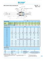
your reliable partner Type 301._ _0 Sizes 1 to 8 We reserve the right to make dimensional and constructional alterations.
Open the catalog to page 9
your reliable partner Mounting flange design with connecting rod k A Type 321._ _0 Sizes 1 to 8 We reserve the right to make dimensional and constructional alterations.
Open the catalog to page 10
your reliable partner Basic element with connecting rod and sleeve We reserve the right to make dimensional and constructional alterations.
Open the catalog to page 11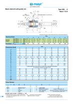
your reliable partner Type 302._ _0 Sizes 1 to 8 We reserve the right to make dimensional and constructional alterations.
Open the catalog to page 12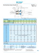
your reliable partner Type 322._ _0 Sizes 1 to 8 We reserve the right to make dimensional and constructional alterations. Order Number Release force 4) Low Medium High Limit switch Without limit switch 3) With integrated limit switch A L2 Length of the guide rod Calculations according to “Length Dimensioning”, see Technical Data, pages 18/19 Example: Order number 2 / 322.410 / L2 = 185 1) Additional sizes for lower or higher release forces 2) H1 max: free stroke in tensile direction 3) EAS®-axial without limit switch on request. Re-engagement force = 20 - 25 % of (larger free strokes on request)...
Open the catalog to page 13
your reliable partner Basic element with guide rod and sleeve We reserve the right to make dimensional and constructional alterations.
Open the catalog to page 14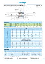
your reliable partner Type 303._ _0 Sizes 1 to 8 We reserve the right to make dimensional and constructional alterations.
Open the catalog to page 15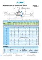
your reliable partner Mounting flange design with connecting rod and guide rod k A Type 323._ _0 Sizes 1 to 8 We reserve the right to make dimensional and constructional alterations.
Open the catalog to page 16
your reliable partner Basic element with connecting rod, guide rod and sleeve We reserve the right to make dimensional and constructional alterations.
Open the catalog to page 17All Chr. Mayr GmbH + Co. KG catalogs and technical brochures
 Robotics and Automation
20 Pages
 Test stand technology
16 Pages
 Steel industry
12 Pages
 Wind energy
24 Pages
 Stage Technology – Applications
20 Pages
 Elevator Brakes
24 Pages
 Machine Tool Components
20 Pages
 EAS®-Sp/Sm/Zr
24 Pages
 EAS®-smartic®
12 Pages
 EAS®-reverse
4 Pages
 EAS®-HTL
8 Pages
 EAS®-HT
28 Pages
 EAS®-HSE
16 Pages
 ROBA®-capping head
12 Pages
 EAS®-dutytorque
8 Pages
 ROBA®-contitorque
12 Pages
 ROBATIC®
60 Pages
 ROBA®-drive-checker
4 Pages
 ROBA®-DS (heavy duty)
80 Pages
 ROBA®-ES
32 Pages
 smartflex®
8 Pages
 ROBA®-DS for torque transducers
16 Pages
 ROBA®-DS (steel)
80 Pages
 ROBA®-DS (servo)
80 Pages
 ROBA®-slip hub
24 Pages
 EAS®-compact® F
32 Pages
 EAS®-compact®
40 Pages
 ROBA®-takt
60 Pages
 ROBA®-SBCplus
4 Pages
 tendo®-PM
44 Pages
 ROBA®-secustop
8 Pages
 ROBA®-twinstop®
12 Pages
 ROBA®-duplostop®
12 Pages
 ROBA®-alphastop®
8 Pages
 ROBA®-topstop®
24 Pages
 ROBA-stop®-stage
4 Pages
 ROBA-stop®-S
12 Pages
 ROBA®-quick
60 Pages
 ROBA®-linearstop H
16 Pages
 ROBA®-linearstop E
16 Pages
 ROBA®-guidestop
32 Pages
 ROBA®-diskstop®
8 Pages
 ROBA-stop®-M Eco
4 Pages
 ROBA-stop-M servo pitch
8 Pages
 ROBA®-linearstop P
16 Pages
 ROBA-stop®-silenzio®
28 Pages
 ROBA-stop®-M
24 Pages
 ROBA®-servostop® Lean
12 Pages
 ROBA®-servostop® Cobot
12 Pages
 ROBA®-servostop® Classic
12 Pages


- Electromotor
- DC electromotor
- Synchronous motor
- 24 V motor
- Flexible coupling
- Shaft shaft coupling
- Permanent magnet motor
- MAYR friction brake
- Flange coupling
- IP54 motor
- Torque coupling
- Transmission coupling
- MAYR disc brake
- MAYR spring brake
- MAYR zero-backlash coupling
- MAYR electromagnetic brake
- IP65 motor
- Friction clutch
- Sleeve coupling