
- Catalogs
- Chenyue (Jiangsu) Technology Co., Ltd.
- ChenYue Worm Gear Reducer CE 0911 MD report EN 60204-1 EN ISO 12100

- Company
- Products
- Catalogs
- News & Trends
- Exhibitions
ChenYue Worm Gear Reducer CE 0911 MD report EN 60204-1 EN ISO 12100

ChenYue Worm Gear Reducer CE 0911 MD report EN 60204-1 EN ISO 12100
This document outlines safety standards and design principles for machinery, focusing on preventing hazards in explosive atmospheres, ensuring stability, maintainability, and ergonomic design, and addressing electrical and pneumatic hazards.
Machinery intended for use in explosive environments should utilize pneumatic or hydraulic systems and intrinsically safe electrical equipment as per IEC 60079-11. Equipment should maintain temperatures well below the flash point for specific products.
Alternative equipment, such as electrical instead of pneumatic systems or water-cutting tools, should be used to minimize noise levels.
Positive mechanical action ensures that a moving component directly moves another, enhancing safety, as seen in switching devices in electrical circuits (IEC 60947-5-1, ISO 14119).
Machines must be designed for stability, considering factors like base geometry, weight distribution, dynamic forces, vibration, and external forces. Stability should be ensured throughout the machine's lifecycle.
Design should facilitate maintenance by ensuring accessibility, ease of handling, and minimizing the need for special tools.
Design should reduce operator stress and strain, considering body sizes, strengths, and postures. Controls should be intuitive, and noise, vibration, and thermal effects minimized.
Electrical equipment design should follow IEC 60204-1 standards to prevent electric shock and ensure safe disconnection and switching.
Design should prevent pressure-related hazards, ensuring compliance with design standards and providing means for depressurization and pressure indication.
Control systems should prevent hazardous behavior through proper design, addressing issues like unexpected start-up and uncontrolled speed changes. Systems should allow safe operator interaction and prevent risks from power interruptions.
Automatic monitoring should ensure safety functions are maintained, detecting faults immediately or through periodic checks to initiate protective measures.
Adjustable guards are permissible only when the hazard zone cannot be fully enclosed for operational reasons. They must be designed to remain fixed during operations and be adjustable without tools.
These guards can be used if they meet all interlocking guard requirements, have a short machine cycle time, and preset maximum opening time. The design must prevent unintended start-up and ensure the guard remains open securely.
Precautions must be taken to prevent hazards from guard construction and movements, such as sharp edges or crushing zones.
Protective devices must be selected or designed to ensure correct safety function implementation and meet appropriate standards.
Provisions should allow for alternative safeguards if necessary due to the range of work.
If source emission reduction is inadequate, additional protective measures like enclosures, screens, and silencers for noise, and vibration isolators for vibration, should be implemented.
These include emergency stop functions, escape and rescue measures, isolation and energy dissipation, and safe handling provisions for machinery.
Information must be provided about the machine's intended use, including training needs, protective equipment, and potential risks. It should cover transport, assembly, operation, and maintenance.
Visual and audible signals should warn of impending hazards and be clear, unambiguous, and easily checked.
Machinery must have clear markings for identification, compliance, and safe use, including manufacturer details, maximum speeds, and necessary protective equipment.
- Humidity: Equipment must operate correctly at up to 50% relative humidity at 40°C, with higher humidity allowed at lower temperatures. Condensation should be managed through design or additional measures like heaters or air conditioners.
- Altitude: Equipment should function correctly up to 1000 meters above sea level.
- Contaminants: Protection against dust, acids, corrosive gases, and salts is required.
- Radiation: Additional measures are needed for equipment exposed to ionizing and non-ionizing radiation.
- Vibration and Shock: Effects should be mitigated through suitable equipment selection and mounting.
Equipment must withstand temperatures from -25°C to +55°C, with short-term exposure up to +70°C. Protection against humidity, vibration, and shock is necessary.
Heavy equipment should have provisions for crane handling. Installation must follow supplier instructions and consider ergonomic principles.
- Incoming Supply: Preferably a single supply, with additional supplies derived from the machine's equipment. Terminals must be clearly identified, and no connection between neutral and protective bonding circuits is allowed, except in specific systems.
- Protective Earthing: A terminal for earthing must be provided near phase conductor terminals.
- Supply Disconnecting Device: Must isolate equipment from supply, with clear ON/OFF positions, and be lockable in the OFF position.
Equipment must protect against direct and indirect contact, following IEC 60364-4-41 standards.
For electrical equipment, measures from sections 6.2.2, 6.2.3, and where applicable, 6.2.4 must be applied to prevent direct contact. Exceptions allow for alternative measures like barriers or obstacles as per IEC 60364-4-41. In public areas, protection must meet IP4X or IPXXD standards.
Protection by Enclosures
Live parts should be enclosed to meet IP2X or IPXXB standards. Access to enclosures should require a key or tool, or disconnection of live parts, unless all live parts are protected to IP2X or IPXXB.
Protection by Insulation
Live parts must be insulated to withstand mechanical, chemical, electrical, and thermal stresses.
Protection Against Residual Voltages
Residual voltages over 60V must be discharged within 5 seconds post-disconnection, unless it interferes with equipment function, in which case a warning notice is required.
Protection Against Indirect Contact
Measures include preventing touch voltage or automatic disconnection of supply. Class II equipment or electrical separation can be used to prevent touch voltage.
Protection by Automatic Disconnection
Automatic disconnection should occur quickly enough to prevent hazardous touch voltage durations.
Protection by PELV
PELV circuits must meet specific conditions to protect against electric shock.
Protection of Equipment
Equipment must be protected against overcurrent, overload, abnormal temperature, and other electrical faults. Overcurrent protection should be provided for circuits where current can exceed component ratings.
Overcurrent Protection
Overcurrent protective devices must be installed at points where conductor capacity is reduced. Devices should have a breaking capacity equal to the prospective fault current.
Protection of Motors
Motors must be protected against overheating, with specific measures detailed in the document.
Control circuits supplied from an AC source must use transformers with separate windings. Multiple transformers should have secondary voltages in phase. DC control circuits connected to protective bonding must be supplied from a separate winding or another transformer. Transformers are not mandatory for machines with a single motor starter or up to two control devices.
The nominal control voltage must not exceed 277 V when supplied from a transformer.
Control circuits require overcurrent protection as per specified standards.
- Start Functions: Must energize the relevant circuit.
- Stop Functions: Three categories exist: immediate power removal (uncontrolled stop), controlled stop with power available, and controlled stop with power left available.
- Operating Modes: Machines can have multiple modes. Unauthorized mode selection must be prevented. Mode selection should not initiate operation; a separate start control is required.
- Suspension of Safety Functions: Safety functions can be suspended for maintenance, ensuring protection by disabling other modes.
- Operation: Safety functions and protective measures must be in place for safe operation. Measures should prevent unintended machine movement.
- Emergency Operations: Emergency stop and switching off must override all functions and be reset manually.
- Monitoring: Hazardous movements must be monitored with appropriate devices.
- Hold-to-Run Controls: Require continuous actuation for operation.
- Two-Hand Control: Defined in three types, requiring concurrent actuation and release for safety.
- Enabling Control: Allows operation initiation and prevents operation when deactivated.
- Combined Start and Stop Controls: Should not result in hazardous situations.
Functional requirements for cableless control systems include ensuring commands affect only intended machines and functions. Stop functions must be clearly identifiable and not labeled as emergency stops. Measures must prevent unauthorized use and ensure safe operation in case of faults or signal loss.
Interlocking safeguards must not initiate hazardous operations. Exceeding operating limits should trigger appropriate control actions. Auxiliary functions must be checked for correct operation to prevent hazards.
1. Interlocks and Coordination: Machines requiring interrelated functions for safety or continuous operation must have suitable interlocks. For groups of machines with multiple controllers, coordination of operations is necessary.
2. Mechanical Brake Actuator Failures: Interlocks should be provided to switch off machine actuators if a brake actuator failure could lead to a hazardous situation.
Reverse Current Braking
Braking by current reversal must include measures to prevent the motor from starting in the opposite direction if it could cause hazards or damage. Time-based devices are not permitted for this purpose.
Control Functions in the Event of Failure
1. General Requirements: Measures must be taken to minimize the probability of failures in electrical equipment that could cause hazards or damage.
2. Risk Minimization Measures: Use proven circuit techniques, redundancy, and diversity to reduce failure risks. Functional tests should be conducted automatically or manually.
Protection Against Maloperation
1. Earth Faults: Control circuits should prevent unintentional starting or hazardous motions due to earth faults.
2. Voltage Interruptions: Systems using memory devices must ensure proper functioning during power failures.
3. Loss of Circuit Continuity: Measures should be taken to prevent hazards from loss of continuity in safety-related control circuits.
Operator Interface and Control Devices
1. General Device Requirements: Devices should be selected and mounted to minimize inadvertent operation and comply with IEC standards.
2. Location and Mounting: Control devices should be accessible and mounted to minimize damage risk.
3. Protection: Devices should be protected against environmental factors and contaminants.
4. Position Sensors: Sensors should be arranged to avoid damage and ensure reliability.
Push-buttons and Indicator Lights
1. Push-button Colors: Specific colors are designated for different functions to prevent confusion.
2. Indicator Lights: Lights should be color-coded and visible from the operator's position.
Emergency Stop and Switching Off Devices
1. Emergency Stop Devices: These should be accessible and located at necessary points. They must have direct opening operation and be colored RED.
2. Emergency Switching Off Devices: These should be located as necessary for the application.
Devices for emergency switching off include push-button operated switches with palm or mushroom head actuators and pull-cord operated switches. These devices must have direct opening action and may be housed in break-glass enclosures. Actuators should be red, with a yellow background if applicable, to avoid confusion with emergency stop devices.
Enabling control devices should allow operation only when actuated in one position. They must be designed to minimize the possibility of being defeated and should follow ergonomic principles. Two-position and three-position types are specified, with clear functions for each position.
Control gear should be accessible for maintenance and protected against external influences. It should be mounted to facilitate operation and maintenance, with special tools provided if necessary. Devices should be grouped by function and separated from non-electrical parts.
Conductors should be copper, with aluminum used only if the cross-sectional area is at least 16 mm². Insulation types include PVC, rubber, and others, with specific voltage and mechanical strength requirements. Flexible cables should have Class 5 or 6 conductors, and their tensile stress should not exceed specified limits.
Control gear enclosures should provide at least IP22 protection against ingress of solid objects and liquids. Conductor wires and bars should be protected against direct contact and damage, with specific requirements for protective conductor circuits and current collectors.
Conductor bars must have a minimum creepage distance of 30 mm. Special measures should be taken to prevent insulation degradation due to environmental factors like conductive dust or chemical exposure. Conductor systems should be designed to prevent adjacent sections from being energized by current collectors.
Power circuit components such as conductor wires, bars, and slip-ring assemblies must be separated from control circuits and withstand mechanical and thermal stresses. Covers for underground systems should require tools for removal, and metal enclosures must be bonded and connected to protective conductors.
Connections must be secure against loosening, and conductors should run without splices unless impractical. Conductors of different circuits can share ducts if properly insulated. Identification of conductors should be clear, using numbers, colors, or alphanumeric codes. Protective conductors should be marked with green-and-yellow, and neutral conductors with blue.
Conductors inside enclosures should be supported and made of flame-retardant materials. External wiring should maintain enclosure protection levels and be enclosed in suitable ducts. Connections to moving parts should avoid excessive flexing.
Ducts must protect against sharp edges and provide adequate protection against environmental factors. Rigid and flexible conduits should be corrosion-resistant and securely fastened. Cable trunking systems should be rigidly supported and free of unused knockouts.
- Test Voltage: 500V AC
- Ambient Temperature: 25°C
- Test Location: L/N – enclosure outside
- Insulation Resistance: Greater than 100 MΩ
- Test Voltage: 1500V AC
- Test Duration: 1 minute
- Test Location: L/N – enclosure outside
- Observation: Puncture Flash-over
- Tests are performed to ensure compliance with clause 6.2.4.
- Electrical equipment functions are tested, including circuits for electrical safety such as earth fault detection.
- Includes general appearance photos of the Equipment Under Test (EUT).
Catalog excerpts

Dongguan True Safety Testing Co., Ltd. Technical Construction File Prepared For: Room 201, No.20, East of Houjie Avenue, Houjie, Dongguan, Guangdong, China Tel:86-769-85088050 4001086960 E-mail:[email protected] http://www.tst-test.com Page 1 of 91
Open the catalog to page 1
Dongguan True Safety Testing Co., Ltd. Dongguan True Safety Testing Co., Ltd. Room 201, No.20, East of Houjie Avenue, Houjie, Dongguan, Guangdong, China Dongguan True Safety Testing Co., Ltd. Chenyue (Jiangsu) Technology Co., Ltd. 10 Jin Lang Road, Shuyang County, Jiangsu Province, China Test specification Worm Gear Reducer Chenyue (Jiangsu) Technology Co., Ltd. 10 Jin Lang Road, Shuyang County, Jiangsu Province, China Room 201, No.20, East of Houjie Avenue, Houjie, Dongguan, Guangdong, China Tel:86-769-85088050 4001086960 E-mail:tst@tst-test.
Open the catalog to page 2
Dongguan True Safety Testing Co., Ltd. Anticipated voltage fluctuations (if more than 10%).: 10% Indicate of possible future changes in electrical equipment : N.A. Limit of power up to which three-phase AC-motors may be started Yes May number of motor overload detection devices be N.A - if lighting circuit voltage is not obtained directly from the N.A.
Open the catalog to page 3
Dongguan True Safety Testing Co., Ltd. General remarks This report shall not be reproduced except in full without the written approval of the testing laboratory. The test results presented in this report relate only to the item(s) tested. Room 201, No.20, East of Houjie Avenue, Houjie, Dongguan, Guangdong, China Tel:86-769-85088050 4001086960 E-mail:[email protected] http://www.tst-test.com
Open the catalog to page 4
Dongguan True Safety Testing Co., Ltd. Copy of marking plate: Worm Gear Reducer Chenyue (Jiangsu) Technology Co., Ltd. Room 201, No.20, East of Houjie Avenue, Houjie, Dongguan, Guangdong, China Tel:86-769-85088050 4001086960 E-mail:[email protected] http://www.tst-test.com
Open the catalog to page 5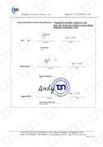
Dongguan True Safety Testing Co., Ltd. Name and address of the testing laboratory : Dongguan True Safety Testing Co., Ltd. Room 201, No.20, East of Houjie Avenue, Houjie, Dongguan, Guangdong, China Technician Title Project Engineer Title AndyZheng/Manager Name and Title Room 201, No.20, East of Houjie Avenue, Houjie, Dongguan, Guangdong, China Tel:86-769-85088050 4001086960 E-mail:[email protected] http://www.tst-test.com
Open the catalog to page 6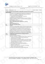
Report No.: TCF20230980171-1SR Dongguan True Safety Testing Co., Ltd.
Open the catalog to page 7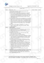
Dongguan True Safety Testing Co., Ltd.
Open the catalog to page 8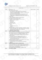
Dongguan True Safety Testing Co., Ltd.
Open the catalog to page 9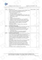
Dongguan True Safety Testing Co., Ltd.
Open the catalog to page 10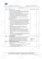
Dongguan True Safety Testing Co., Ltd.
Open the catalog to page 11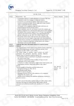
Dongguan True Safety Testing Co., Ltd.
Open the catalog to page 12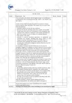
Dongguan True Safety Testing Co., Ltd.
Open the catalog to page 13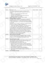
Report No.: TCF20230980171-1SR Dongguan True Safety Testing Co., Ltd.
Open the catalog to page 14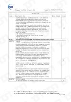
Report No.: TCF20230980171-1SR Dongguan True Safety Testing Co., Ltd.
Open the catalog to page 15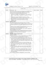
Dongguan True Safety Testing Co., Ltd.
Open the catalog to page 16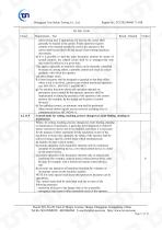
Dongguan True Safety Testing Co., Ltd.
Open the catalog to page 17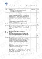
Report No.: TCF20230980171-1SR Dongguan True Safety Testing Co., Ltd.
Open the catalog to page 18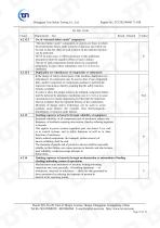
Report No.: TCF20230980171-1SR Dongguan True Safety Testing Co., Ltd.
Open the catalog to page 19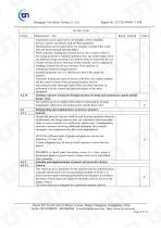
Dongguan True Safety Testing Co., Ltd.
Open the catalog to page 20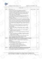
Dongguan True Safety Testing Co., Ltd.
Open the catalog to page 21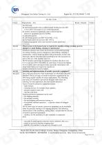
Report No.: TCF20230980171-1SR Dongguan True Safety Testing Co., Ltd.
Open the catalog to page 22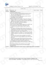
Report No.: TCF20230980171-1SR Dongguan True Safety Testing Co., Ltd.
Open the catalog to page 23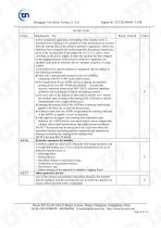
Dongguan True Safety Testing Co., Ltd.
Open the catalog to page 24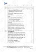
Dongguan True Safety Testing Co., Ltd.
Open the catalog to page 25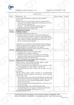
Report No.: TCF20230980171-1SR Dongguan True Safety Testing Co., Ltd.
Open the catalog to page 26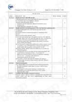
Report No.: TCF20230980171-1SR Dongguan True Safety Testing Co., Ltd.
Open the catalog to page 27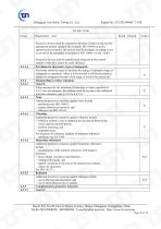
Report No.: TCF20230980171-1SR Dongguan True Safety Testing Co., Ltd.
Open the catalog to page 28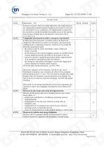
Report No.: TCF20230980171-1SR Dongguan True Safety Testing Co., Ltd.
Open the catalog to page 29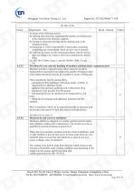
Dongguan True Safety Testing Co., Ltd.
Open the catalog to page 30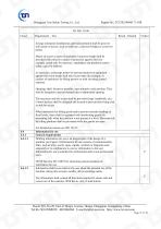
Report No.: TCF20230980171-1SR Dongguan True Safety Testing Co., Ltd.
Open the catalog to page 31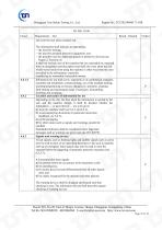
Dongguan True Safety Testing Co., Ltd.
Open the catalog to page 32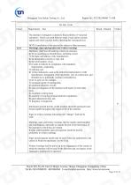
Dongguan True Safety Testing Co., Ltd.
Open the catalog to page 33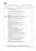
Dongguan True Safety Testing Co., Ltd.
Open the catalog to page 34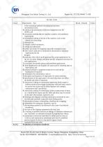
Dongguan True Safety Testing Co., Ltd.
Open the catalog to page 35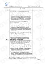
Dongguan True Safety Testing Co., Ltd.
Open the catalog to page 36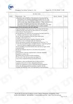
Dongguan True Safety Testing Co., Ltd.
Open the catalog to page 37
Report No.: TCF20230980171-1SR Dongguan True Safety Testing Co., Ltd.
Open the catalog to page 38
Dongguan True Safety Testing Co., Ltd.
Open the catalog to page 39
Dongguan True Safety Testing Co., Ltd.
Open the catalog to page 40
Dongguan True Safety Testing Co., Ltd.
Open the catalog to page 41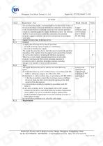
Dongguan True Safety Testing Co., Ltd.
Open the catalog to page 42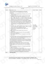
Dongguan True Safety Testing Co., Ltd.
Open the catalog to page 43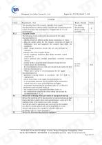
Dongguan True Safety Testing Co., Ltd.
Open the catalog to page 44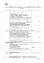
Dongguan True Safety Testing Co., Ltd.
Open the catalog to page 45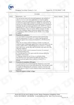
Dongguan True Safety Testing Co., Ltd.
Open the catalog to page 46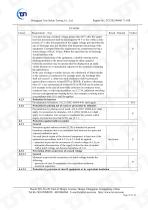
Report No.: TCF20230980171-1SR Dongguan True Safety Testing Co., Ltd.
Open the catalog to page 47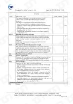
Report No.: TCF20230980171-1SR Dongguan True Safety Testing Co., Ltd.
Open the catalog to page 48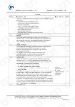
Dongguan True Safety Testing Co., Ltd.
Open the catalog to page 49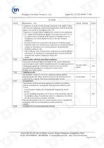
Dongguan True Safety Testing Co., Ltd.
Open the catalog to page 50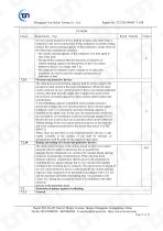
Dongguan True Safety Testing Co., Ltd.
Open the catalog to page 51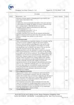
Dongguan True Safety Testing Co., Ltd.
Open the catalog to page 52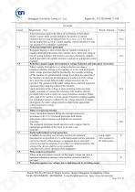
Dongguan True Safety Testing Co., Ltd.
Open the catalog to page 53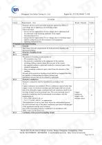
Report No.: TCF20230980171-1SR Dongguan True Safety Testing Co., Ltd.
Open the catalog to page 54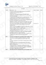
Dongguan True Safety Testing Co., Ltd.
Open the catalog to page 55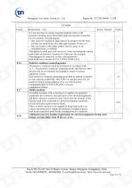
Dongguan True Safety Testing Co., Ltd.
Open the catalog to page 56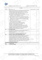
Report No.: TCF20230980171-1SR Dongguan True Safety Testing Co., Ltd.
Open the catalog to page 57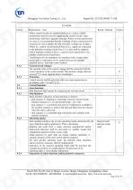
Report No.: TCF20230980171-1SR Dongguan True Safety Testing Co., Ltd.
Open the catalog to page 58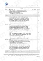
Report No.: TCF20230980171-1SR Dongguan True Safety Testing Co., Ltd.
Open the catalog to page 59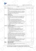
Report No.: TCF20230980171-1SR Dongguan True Safety Testing Co., Ltd.
Open the catalog to page 60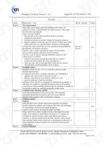
Report No.: TCF20230980171-1SR Dongguan True Safety Testing Co., Ltd.
Open the catalog to page 61
Dongguan True Safety Testing Co., Ltd.
Open the catalog to page 62
Report No.: TCF20230980171-1SR Dongguan True Safety Testing Co., Ltd.
Open the catalog to page 63
Report No.: TCF20230980171-1SR Dongguan True Safety Testing Co., Ltd.
Open the catalog to page 64
Report No.: TCF20230980171-1SR Dongguan True Safety Testing Co., Ltd.
Open the catalog to page 65
Report No.: TCF20230980171-1SR Dongguan True Safety Testing Co., Ltd.
Open the catalog to page 66
Dongguan True Safety Testing Co., Ltd.
Open the catalog to page 67
Report No.: TCF20230980171-1SR Dongguan True Safety Testing Co., Ltd.
Open the catalog to page 68
Report No.: TCF20230980171-1SR Dongguan True Safety Testing Co., Ltd.
Open the catalog to page 69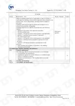
Report No.: TCF20230980171-1SR Dongguan True Safety Testing Co., Ltd.
Open the catalog to page 70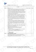
Dongguan True Safety Testing Co., Ltd.
Open the catalog to page 71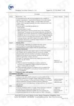
Dongguan True Safety Testing Co., Ltd.
Open the catalog to page 72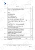
Dongguan True Safety Testing Co., Ltd.
Open the catalog to page 73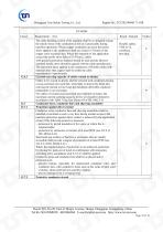
Report No.: TCF20230980171-1SR Dongguan True Safety Testing Co., Ltd.
Open the catalog to page 74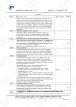
Report No.: TCF20230980171-1SR Dongguan True Safety Testing Co., Ltd.
Open the catalog to page 75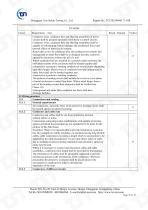
Report No.: TCF20230980171-1SR Dongguan True Safety Testing Co., Ltd.
Open the catalog to page 76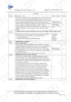
Report No.: TCF20230980171-1SR Dongguan True Safety Testing Co., Ltd.
Open the catalog to page 77All Chenyue (Jiangsu) Technology Co., Ltd. catalogs and technical brochures
 RV-RW-VF-PC-WF catalogue
28 Pages
 CYCM catalogue
18 Pages



- Planetary gearbox
- Coaxial gearhead
- Precision gearhead
- Right angle gearhead
- Compact gearhead
- Solid-shaft gearhead
- Hollow-shaft gearhead
- Gear train gear reducer
- Gearbox for industrial applications
- Transmission gearhead
- Multi-stage gearhead
- Single-stage gearhead
- Shaft gearhead
- Helical gear gearhead
- Machines gearbox
- Dual-stage gearbox
- High-performance gearhead
- Low-noise gearhead
- Low-backlash gearhead
- Clamp gearbox